Interface
This guide introduces the driver and control methods for common interfaces of the NG4500 series devices, including GPIO, I2C, SPI, CAN, USB, and UART. It focuses on hardware resource allocation, typical application scenarios, and basic operation commands.
GPIO
For the detailed configuration, please refer to Jetson Orin NX Series and Jetson Orin Nano Series Pinmux
- IO Board Configuration Table:
| Pin # | Signal Name | Description | Direction | Pin Type |
|---|---|---|---|---|
| 218 | GPIO12 | GPIO=Low/high when IN1=high(Open)/low(Short) | Input | dry contact |
| IN1_COM: COM pin | ||||
| 216 | GPIO11 | IN2: GPIO=Low/high when IN1=high(Open)/low(Short) | Input | dry contact |
| IN2_COM: COM pin | ||||
| 206 | GPIO07 | IN3: GPIO=Low/high when IN1=high(Open)/low(Short) | Input | dry contact |
| IN3_COM: COM pin | ||||
| 228 | GPIO13 | IN4: GPIO=Low/high when IN1=high(Open)/low(Short) | Input | dry contact |
| IN4_COM: COM pin | ||||
| 199 | I2S0_SCLK_1V8 | OUT1: GPIO=Low for short, high for open | Output | dry contact |
| OUT1_COM: COM pin | ||||
| 197 | I2S0_LRCK_1V8 | OUT2: GPIO=Low for short, high for open | Output | dry contact |
| OUT2_COM: COM pin | ||||
| 195 | I2S0_SDIN_1V8 | OUT3: GPIO=Low for shor, high for open. | Output | dry contact |
| OUT3_COM: COM pin | ||||
| 193 | I2S0_SDOUT_1V8 | OUT4: GPIO=Low for short, high for open. | Output | dry contact |
| OUT4_COM: COM pin |
Usage
- Run
gpioinfocommand to query the GPIO mapping and status:
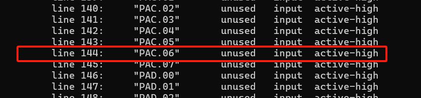
- Run
gpiosetas below to control GPIO output:
# To set GPIO12 to HIGH
sudo gpioset --mode=wait gpiochip0 144=1
# To set GPIO12 to LOW
sudo gpioset --mode=wait gpiochip0 144=0
UART
UART Instances Table
| Usage on Orin nano/NX | UART Instance | Base Address | Ball Name | Bus Name | DTS status | DTS alias |
|---|---|---|---|---|---|---|
| Debug | UARTC | 0x0c280000 | UART2 | ttyTCU0 | OK | serial0 |
| RS485 | UARTA | 0x03100000 | UART1 | ttyTHS1 | OK | serial1 |
| RS232 | UARTB | 0x03110000 | UART0 | ttyTHS3 | OK | serial3 |
-
Debug(ttyTCU0)
-
Hardware Connection:Connect to computer by using debug cable.
-
Serial Port Settings:Baud rate 115200, 8-bits data, 1 stop bit, no parity bit, no flow control.
-
Common terminal tools:PuTTY and Xshell for Windows ; minicom and screen for Linux.
-
-
RS232
- Hardware Pin Definition
Pin Signal Name Description Direction Pin Type 99 UART0_TXD Use for uart Ransmit (with 3.3 level shifter) Output CMOS – 1.8V 101 UART0_RXD Use for uart Receive (with 3.3 level shifter) Input CMOS – 1.8V -
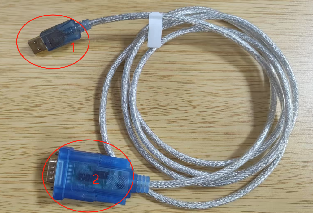
Hardware Connection
- Use Connector 1 to connect to the PC, and Connector 2 to connect to the Jetson RS232 TX/RX.
- Ensure proper voltage level shifting is applied to prevent hardware damage.
-
RS485
- Hardware Pin Definition
Pin Signal Name Description Direction Pin Type 203 UART1_TXD Use for RS_485 Output CMOS 1.8V 205 UART1_RXD Use for RS_485 Input CMOS 1.8V 207 UART1_RTS* RS_485 enable pin Output CMOS 1.8V - Install dependencies
sudo apt-get update
sudo apt-get install gpiod libgpiod-dev- Type the following command to testing RS458
gcc -o rs485_test rs485_test.c -lgpiod- Run the following command
sudo ./rs485_test [TTY_DIR] [DE_CHIP] [DE_LINE]
# Run
sudo ./rs485_test /dev/ttyTHS1 /dev/gpiochip0 112- Function Description
- After startup, enter
sendto switch to send mode. Type your message and press Enter to send. - Enter
recvto switch to received mode,display the content received via the serial port - Enter
quitto exit the program.
- After startup, enter
-
Sample Code
#include <stdio.h>
#include <stdlib.h>
#include <string.h>
#include <sys/stat.h>
#include <errno.h>
#include <unistd.h>
#include <fcntl.h>
#include <termios.h>
#include <gpiod.h>
#include <linux/serial.h>

#define BUFFER_SIZE 256
#define RS485_CONSUMER "RS485_program"

struct gpiod_chip *chip;
struct gpiod_line *rts_line;

void setup_gpio(char *gpio_chip, int gpio_line)
{
    int ret;

    chip = gpiod_chip_open(gpio_chip);
    if (!chip) {
        fprintf(stderr, "gpiod_chip_open");
        exit(EXIT_FAILURE);
    }

    rts_line = gpiod_chip_get_line(chip, gpio_line);
    if (!rts_line) {
        fprintf(stderr, "Failed to get GPIO line %d\n", gpio_line);
        gpiod_chip_close(chip);
        exit(EXIT_FAILURE);
    }

    ret = gpiod_line_request_output(rts_line, RS485_CONSUMER, 0);
    if (ret < 0) {
        fprintf(stderr, "Failed to request GPIO line as output: %s\n", strerror(-ret));
        gpiod_chip_close(chip);
        exit(EXIT_FAILURE);
    }
}

void set_rts_high() {
    gpiod_line_set_value(rts_line, 1);
    int value = gpiod_line_get_value(rts_line);
    printf("RTS set to HIGH, actual value: %d\n", value);
}

void set_rts_low() {
    gpiod_line_set_value(rts_line, 0);
    int value = gpiod_line_get_value(rts_line);
    printf("RTS set to LOW, actual value: %d\n", value);
}

int main(int argc, char* argv[]) {
    int tty_fd;
    char *tty_name;
    struct termios tty;
    char buffer[BUFFER_SIZE];
    ssize_t n;
    int ready;
    fd_set readfds;
    int rts_line_num;
    char *gpio_chip;
    int mode = 0;

    if (argc < 4) {
        printf("Usage: %s /dev/ttyTHS1 GPIO_CHIP(/dev/gpiochip*) RTS_LINE\n", argv[0]);
        return 1;
    }

    tty_name = argv[1];
    gpio_chip = argv[2];
    rts_line_num = atoi(argv[3]);

    setup_gpio(gpio_chip, rts_line_num);

    tty_fd = open(tty_name, O_RDWR | O_NOCTTY | O_NDELAY);
    if (tty_fd < 0) {
        perror("Unable to open serial port");
        return 1;
    }

    tcgetattr(tty_fd, &tty);
    cfmakeraw(&tty);
    cfsetispeed(&tty, B9600);
    cfsetospeed(&tty, B9600);
    tcsetattr(tty_fd, TCSANOW, &tty);

    printf("Serial port %s opened successfully, fd: %d\n", tty_name, tty_fd);

    while (1) {
        FD_ZERO(&readfds);
        FD_SET(tty_fd, &readfds);
        FD_SET(STDIN_FILENO, &readfds);

        ready = select(tty_fd + 1, &readfds, NULL, NULL, NULL);
        if (ready == -1) {
            perror("select");
            break;
        }

        if (FD_ISSET(tty_fd, &readfds)) {
            set_rts_low();
            n = read(tty_fd, buffer, BUFFER_SIZE - 1);
            if (n > 0) {
                buffer[n] = '\0';
                printf("Received: %s\n", buffer);
            }
        }

        if (FD_ISSET(STDIN_FILENO, &readfds)) {
            if (fgets(buffer, BUFFER_SIZE, stdin) != NULL) {
                buffer[strcspn(buffer, "\n")] = '\0';

                if (strcmp(buffer, "send") == 0) {
                    mode = 1;
                    printf("Switched to SEND mode\n");
                    continue;
                } else if (strcmp(buffer, "recv") == 0) {
                    mode = 0;
                    printf("Switched to RECEIVE mode\n");
                    continue;
                } else if (strcmp(buffer, "quit") == 0) {
                    break;
                }

                if (mode == 1) {
                    set_rts_high();
                    usleep(10000);
                    write(tty_fd, buffer, strlen(buffer));
                    tcdrain(tty_fd);
                    set_rts_low();
                } else {
                    printf("Invalid command in RECEIVE mode\n");
                }
            }
        }
    }

    close(tty_fd);
    gpiod_line_release(rts_line);
    gpiod_chip_close(chip);

    return 0;
}
SPI
- Hardware Pin Definition
| Pin | Signal Name | Description | Direction | Pin Type |
|---|---|---|---|---|
| 106 | SPI1_SCK | SPI 1 Clock | Bidir | CMOS – 3.3V |
| 108 | SPI1_MISO | SPI 1 Master In / Slave Out | Bidir | CMOS – 3.3V |
| 104 | SPI1_MOSI | SPI 1 Master Out / Slave In | Bidir | CMOS – 3.3V |
| 110 | SPI1_CS0* | SPI 1 Chip Select 0 | Bidir | CMOS – 3.3V |
| 112 | SPI1_CS1* | SPI 1 Chip Select 1 | Bidir | CMOS – 3.3V |
-
Hardware Connection:Shorting MOSI and MISO for loopback testing.
-
Enabling and Configuring SPI
- To start the configuration tool, run this commands:
sudo python /opt/nvidia/jetson-io/jetson-io.py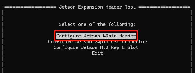
-Select
Configure Jetson 40pin Header
-
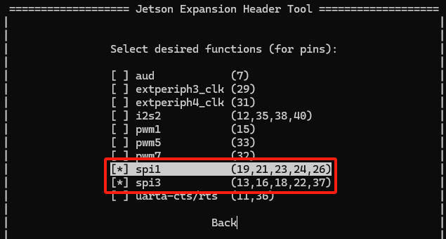
Select
Configure header pins manually
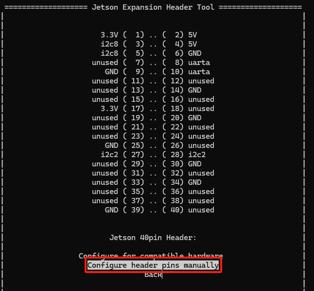
-
Click Spacebar and then select SPI1 and SPI3,after which SPI will be enabled
-
Return and select
Save and reboot to reconfigure pins,take effect after reboot.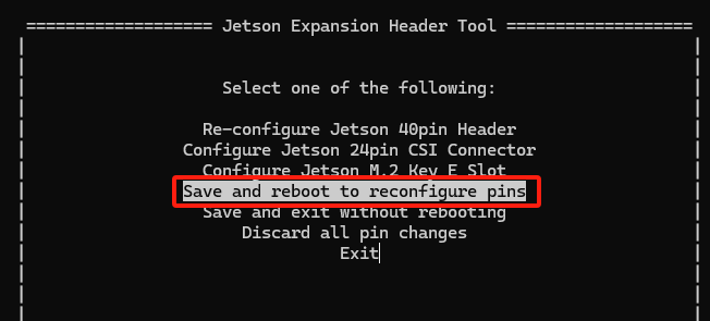
- To start the configuration tool, run this commands:
-
Testing SPI Communication :
# Get spi code
git clone https://github.com/rm-hull/spidev-test
cd spidev-test/
gcc spidev_test.c -o spidev_test

# testing
./spidev_test -v -D /dev/spidev0.0 -p "Test"
CAN
- Hardware Pin Definition
| Pin | Signal Name | Description | Direction | Pin Type |
|---|---|---|---|---|
| 145 | CAN_TX | FD CAN Transmit | Output | CMOS – 3.3V |
| 143 | CAN_RX | FD CAN Receive | Input | CMOS – 3.3V |
- Hardware Connection:Connect two CAN bus systems with D+ to D+ and D- to D-.
Software Installation
- Install
can-utils
sudo apt update
sudo apt-get install can-utils
- Refer to the code below for testing:
# Check the connection status
ip link show can0

# Configure the interface and set the baud rate to 100kbps
sudo ip link set can0 up type can bitrate 100000

# Check the can0 data
candump can0

# send data
cansend can0 123#11.22.33.44
RTC
RTC Setting
- Set the time and date
sudo hwclock --set --date="2000-01-01 12:00:00"
- Verify the RTC Time
sudo hwclock -r
- Update the system time to match the RTC time
# system time → RTC
sudo hwclock --systohc

# RTC → system time
sudo hwclock --hctosys
- Verify the system time
date
- Update the Network time to match the RTC time
# If unable to set the RTC, check if the NTP service is running and properly configured
# Disable the NTP service
sudo systemctl stop systemd-timesyncd.service
sudo timedatectl set-ntp false
Camera
-
The following section describes how to initialize and configure the camera module, using
imx219as an example. The hardware connection is shown below: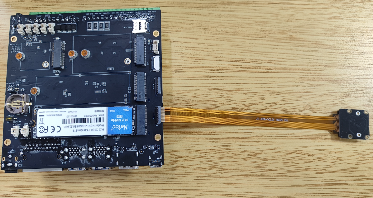
-
Use the
config-by-hardware.pyto enable the camera,The changes will take effect after a reboot.- List Available Hardware Modules
# List Available Hardware Modules
sudo python /opt/nvidia/jetson-io/config-by-hardware.py -l
#Example Output:
Header 1 [default]: Jetson 40pin Header
  Available hardware modules:
  1. Adafruit SPH0645LM4H
  2. Adafruit UDA1334A
  3. FE-PI Audio V1 and Z V2
  4. ReSpeaker 4 Mic Array
  5. ReSpeaker 4 Mic Linear Array
Header 2: Jetson 24pin CSI Connector
  Available hardware modules:
  1. Camera IMX219 Dual
  2. Camera IMX219 Dual CamThink
  3. Camera IMX219-A
  4. Camera IMX219-A and IMX477-C
  5. Camera IMX219-C
  6. Camera IMX477 Dual
  7. Camera IMX477 Dual 4 lane
  8. Camera IMX477-A
  9. Camera IMX477-A and IMX219-C
  10. Camera IMX477-C
Header 3: Jetson M.2 Key E Slot
  No hardware configurations found!
- Select and Configure the IMX219 Dual CamThink Module
# Select and Configure the IMX219 Dual CamThink Module
# -n specifies Header Number,Camera IMX219 Dual CamThink is the dtbo overlay-name
sudo python /opt/nvidia/jetson-io/config-by-hardware.py -n 2='Camera IMX219 Dual CamThink'
- Connect a USB keyboard and mouse, launch a terminal, and run the following commands:
# Install required multimedia packages
sudo apt update
sudo apt install -y nvidia-l4t-gstreamer nvidia-l4t-jetson-multimedia-api

# Launch the camera
nvgstcapture-1.0