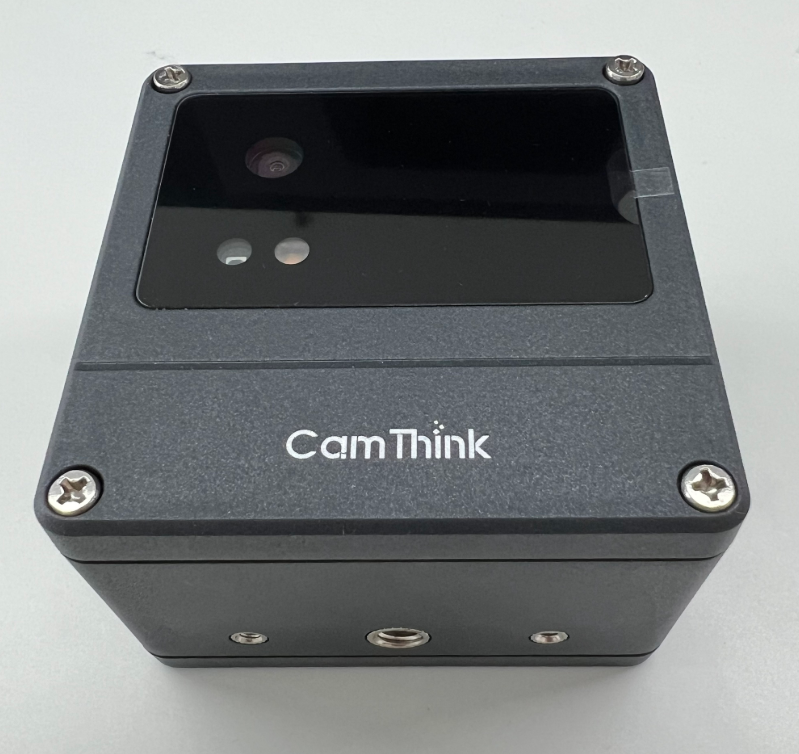
Dev Kit Installation Guide
Component Overview
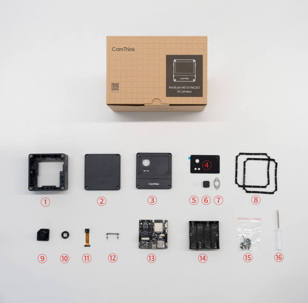
Component parts: ① NE101_Middle Frame ② NE101_Bottom Cover ③ NE101_Top Cover ④ NE101_M6 Panel ⑤ X1_Lens ⑥ NE101_Button ⑦ NE101_Pressure Plate ⑧ NE101_Sealing Ring ⑨ M6 Lens Support Base ⑩ NE101_M6 Dust Cover ⑪ M6 Image Module (OV5640) ⑫ CV Light Board ⑬ Mainboard (WIFI Version) ⑭ Battery Box ⑮ Screw Package: Standard version includes four types of screws, see parts list below for details ⑯ Screwdriver
If you don't have an NE101 yet, you can purchase it through the official website — NE101 Developer Kit Purchase Link.
Parts Checklist
After receiving the device, you can verify the components against the following checklist:
| Component Group | Part Name | Quantity | Notes |
|---|---|---|---|
| Housing | NE101_Top Cover | 1 | |
| NE101_Middle Frame | 1 | ||
| NE101_Bottom Cover | 1 | ||
| NE101_Button | 1 | ||
| NE101_Sealing Ring | 2 | One each for top and bottom covers | |
| NE101_Pressure Plate | 1 | Pressure plate for button | |
| NE101_M6 Panel | 1 | Top cover panel, for attaching to top cover, standard lens panel | |
| NE101_M12 Panel (Optional) | 1 | Panel for USB lens | |
| Boards | Mainboard (WIFI Version) | 1 | Includes chip, standard version comes with OV5640 120° 3M lens |
| M6 Image Module | 1 | ||
| CV Light Board | 1 | Connects to the mainboard | |
| Extension Board: Cat-1 (Optional) | 1 | ||
| Extension Board: POE (Optional) | 1 | ||
| Screws | Phillips Machine Screws (Thin Cylindrical Head, Original Color) | 8 | Screws for top and bottom covers |
| Phillips Self-tapping Screws (Pointed Tail, Carbon Steel, Galvanized) | 4 | Screws for fixing the mainboard | |
| Phillips Self-tapping Screws (Flat Tail, Carbon Steel, Black) | 2 | Screws for button pressure plate | |
| Phillips Self-tapping Screws (Pointed Tail, Carbon Steel, Silver) | 2 | Screws for battery compartment | |
| Phillips Self-tapping Screws - USB Lens Module Fixing Screws (Optional) | 2 | Unique to USB module lens, used for diagonal locking; in this case, mainboard screws are reduced from four to three | |
| Other Parts | Battery Box | 1 | Standard version defaults to battery power |
| NE101_M6 Dust Cover | 1 | Placed between panel and lens, not needed for USB version | |
| M6 Lens Support Base | 1 | Placed between mainboard and OV5640 base | |
| X1_Lens | 1 | Frosted light board lens, placed between light board and panel |
—If you purchased the standard version, you don't need to worry about optional accessories.
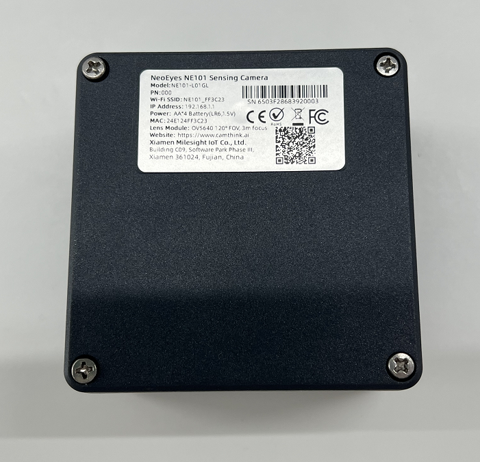
Please Note: ① Batteries are not included in the shipment; you need to purchase four AA batteries separately ② The standard configuration includes an OV5640 module lens with key parameters: 120° FOV, 3m Focus ③ If you choose to use a USB module lens, two additional fixing screws are included for the module's two diagonal corners, and the mainboard screws are reduced from four to three.
Installation Steps
After checking the parts list and quantities, you can assemble the individual components to further confirm the completeness of the parts. Specifically, these are the top cover (four screws, lens protection foam, panel, X1 lens), middle frame (button pressure plate, button, two screws), bottom cover (four screws), battery box (requires four AA batteries), and mainboard (standard version OV5640 lens module, M6 lens support base, four screws), totaling five parts.
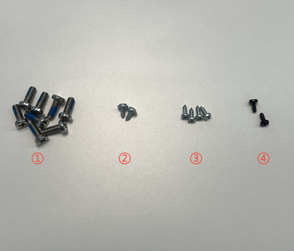
The kit includes four types of screws: ① Phillips Machine Screws (Thin Cylindrical Head, Original Color) ② Phillips Self-tapping Screws (Pointed Tail, Carbon Steel, Silver) ③ Phillips Self-tapping Screws (Pointed Tail, Carbon Steel, Galvanized) ④ Phillips Self-tapping Screws (Flat Tail, Carbon Steel, Black)
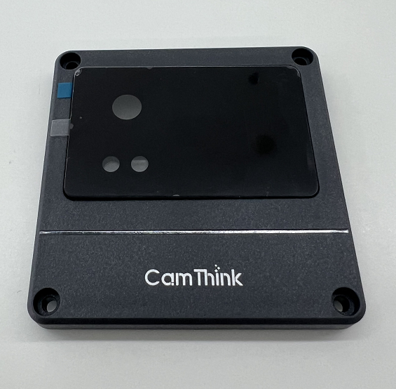
Step 1: Top Cover Assembly
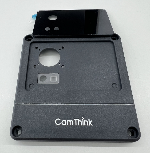
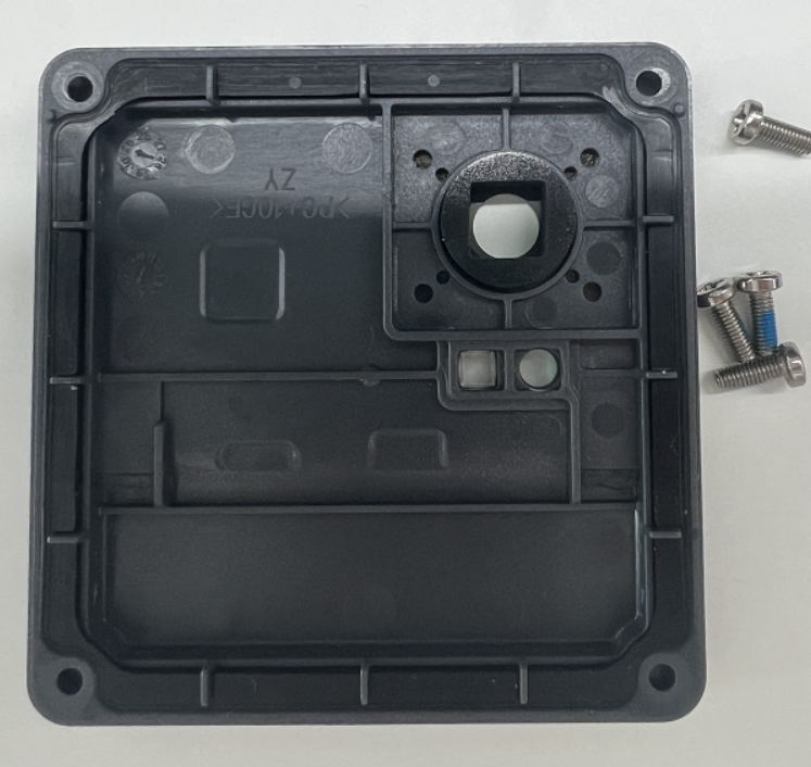
Top cover components: Includes M6 panel, X1 lens (for the light board), four screws for fixing to the middle frame, and sealing ring.
First, place the sealing ring in the groove on the inside of the top cover, then insert the white transparent X1 lens into the two holes in the top cover (one round and one square). Next, peel off the adhesive backing from the panel and stick it to the groove in the top cover, making sure the holes are aligned. The lens will also be fixed to the panel. Finally, remove the protective film from the front of the panel before use to ensure clarity.
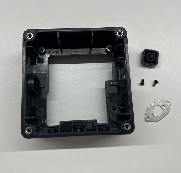
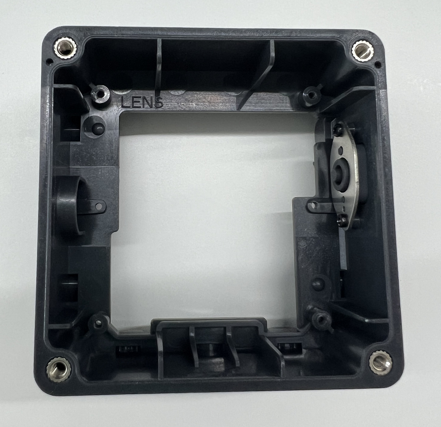
Step 2: Middle Frame Assembly
Middle frame components: NE101_Button, NE101_Sealing Ring, NE101_Pressure Plate.
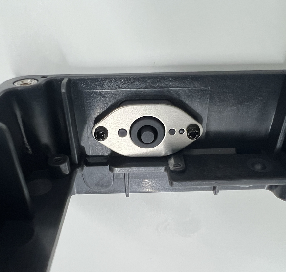
First, install the button on the side of the middle frame with the camera icon facing outward, then place the pressure plate over the button while passing through the cylinders on both sides, and finally secure it with two screws. Please note that the screws fixing the button should be tightened as much as possible to prevent the button from becoming loose or misaligned.
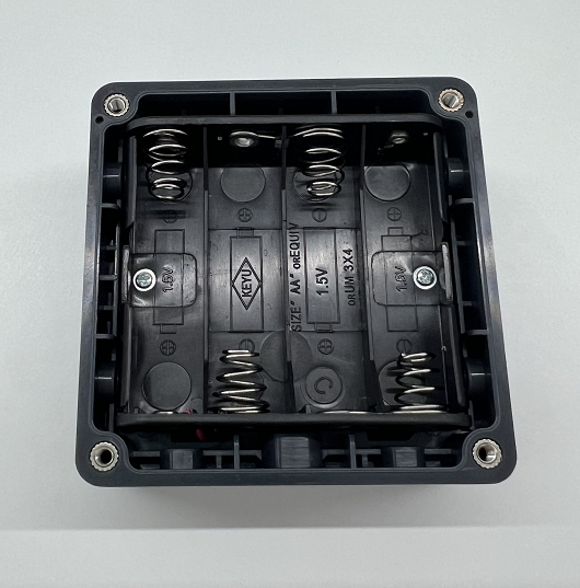
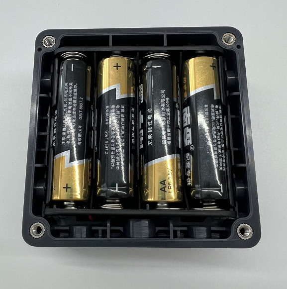
Step 3: Battery Box Assembly
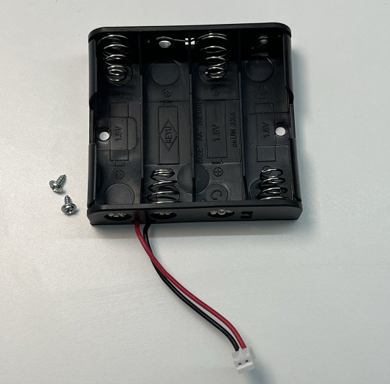
Battery box components: The standard version is powered by batteries, with the battery box fixed to the middle frame using two screws through the screw holes inside the battery box. The battery compartment connection wire connects to the power interface on the back of the mainboard.
Step 4: Bottom Cover Assembly
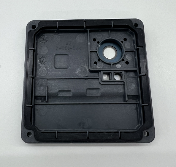
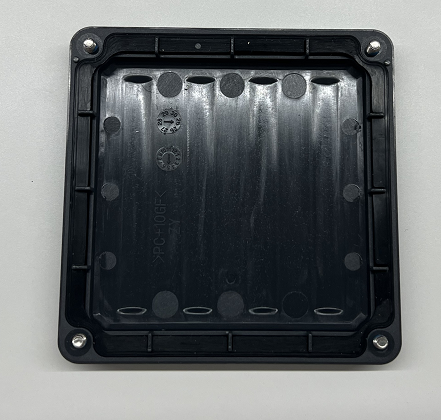
Bottom cover components: Place the sealing ring in the groove on the inside of the bottom cover and prepare the four screws for the bottom cover.
Step 5: Mainboard Assembly
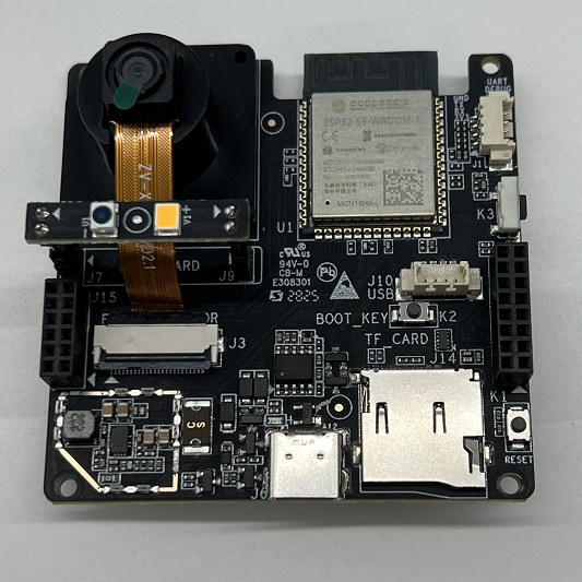
Mainboard components: Includes M6 lens support base, OV5640 lens module, CV light board for use with the lens, and four screws for fixing to the middle frame.
Fixing the Camera Module Support Base
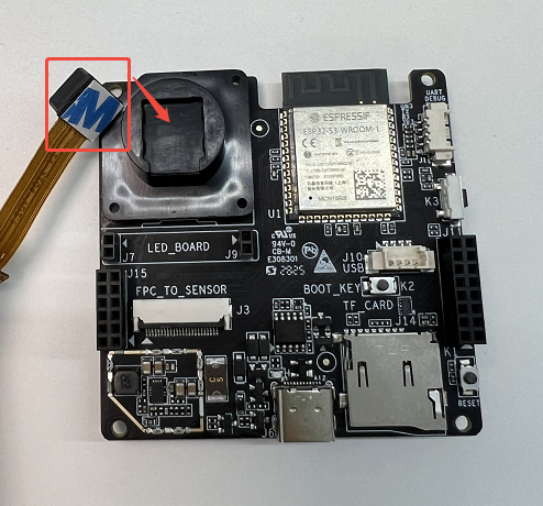
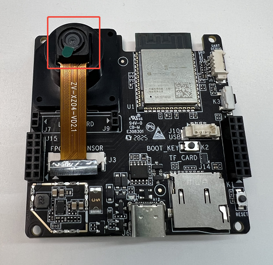
First, install the M6 lens support base with the notch facing downward onto the socket in the upper left corner of the mainboard. Secure it to the mainboard using adhesive, then peel off the double-sided tape on the back of the lens module and stick it to the support base. At the same time, place the dust cover over the lens and stick it in place, or directly stick it to the front cover panel to protect the lens.
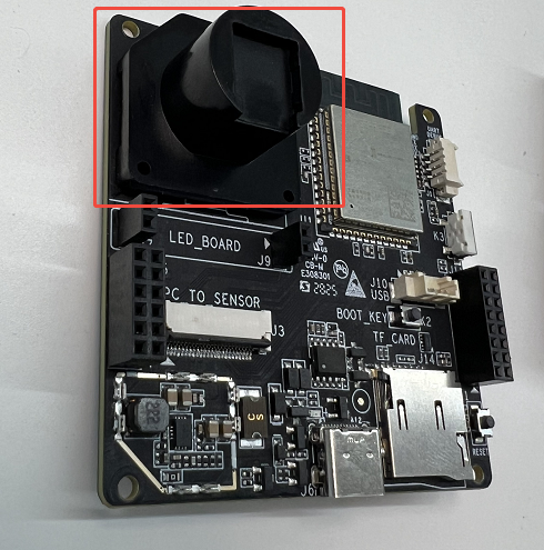
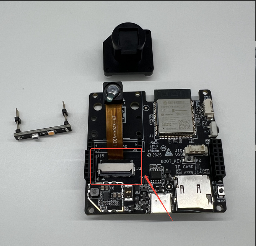
Fixing the Camera Module and Light Board
Next, connect the data cable of the lens module to the MIPI CSI clip and secure it. This clip is a flap that secures the module connection cable by lifting up and pressing down. Finally, below the camera module, insert the pins of the CV light board into the mainboard, with the round light sensor on the left and the square fill light on the right. After everything is installed, you can remove the protective film from the module lens.
—Final result of the mainboard assembly:
Please Note: ① If you are using the assembly for development and debugging, it is recommended to secure the lens module with double-sided tape ② If you are assembling for immediate application deployment, it is recommended to use hot melt adhesive or soldering methods.
In addition to the standard camera module, you can choose the most suitable lens module for flexible deployment based on installation height, space size, and recognition targets. You can significantly improve visual effects with a low-cost upgrade by simply replacing the lens module without changing the mainboard. Below are the supported camera module specifications:
| Type | Model | Field of View | Focus Distance | Application Scenario |
|---|---|---|---|---|
| CPI Camera | OV5640 | 60° | 15cm | Close-range shooting |
| CPI Camera | OV5640 | 60° | 4m | Standard distance shooting |
| CPI Camera | OV5640 | 120° | 8cm | Close-range wide-angle shooting |
| CPI Camera | OV5640 | 120° | 3m | Standard distance wide-angle shooting |
| USB Camera | SC200AI-51-4M | 51° | 4m | Standard angle shooting |
| USB Camera | SC200AI-88-3M | 88° | 3m | Wide angle shooting |
| USB Camera | SC200AI-137-2M | 137° | 2m | Ultra-wide angle shooting |
To learn more, see — Supported Interchangeable Camera Modules.
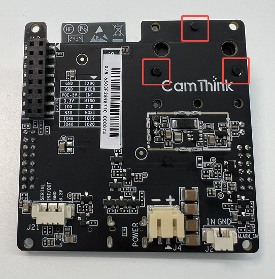
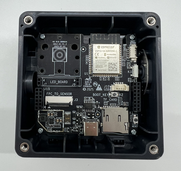
Step 6: Fixing the Mainboard
After the mainboard components are installed, you can secure the mainboard to the middle frame using four screws in the screw holes. Note that the screws used are pointed tail, carbon steel, galvanized. The orientation of the mainboard in the middle frame needs to align with the button, and you can verify during installation by pressing the external button. To clearly show the mainboard fixation, the camera module and light board on the mainboard from the previous step have been removed, as shown in the image below.
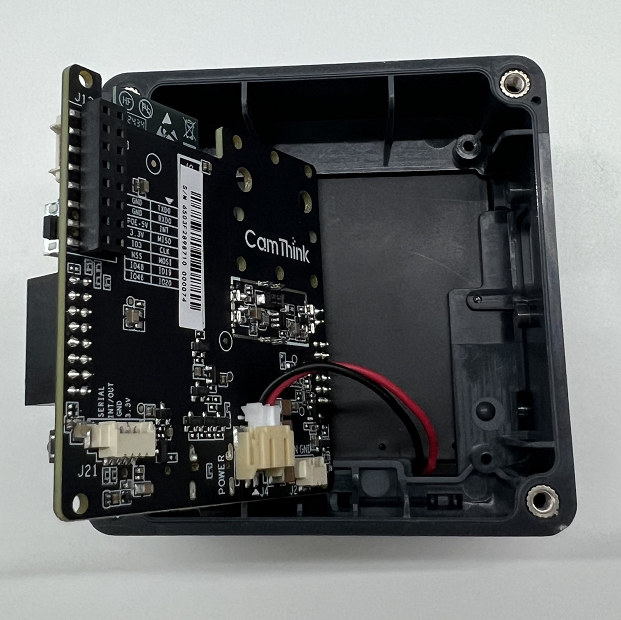
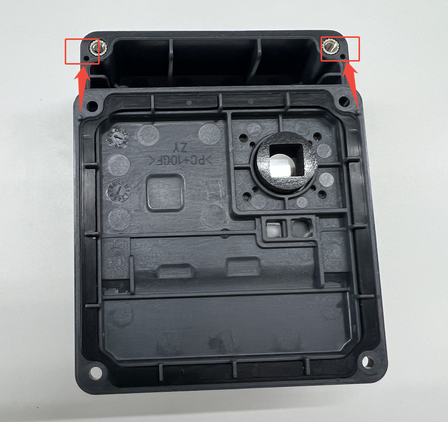
Step 7: Fixing the Battery Box
After securing the mainboard to the middle frame, connect the external wire of the battery box to the power interface on the back of the mainboard, as shown in the image below. Then secure the battery box to the middle frame using two screws through the screw holes inside the battery box. The screws used are pointed tail, carbon steel, silver. Finally, insert the batteries. At this point, the middle frame, mainboard, and battery components are all secured.
Step 8: Securing the Top and Bottom Covers
Finally, align the top and bottom covers with the holes in the middle frame and secure each with four screws to complete the assembly.
Important Detail: When installing, make sure that the raised circular parts of the top and bottom covers correspond to the recessed parts of the middle frame. If installed incorrectly, there will be gaps between the top/bottom covers and the middle frame.
At this point, your NE101 Sensing Camera Developer Kit is fully assembled and ready to use. For specific usage methods and deployment, see — Quick Start.
If you have any questions or suggestions, feel free to join our Discord community or provide feedback through our GitHub Issues to communicate and share with other developers — Discord.