Dev Kit Installation Guide
Component Overview
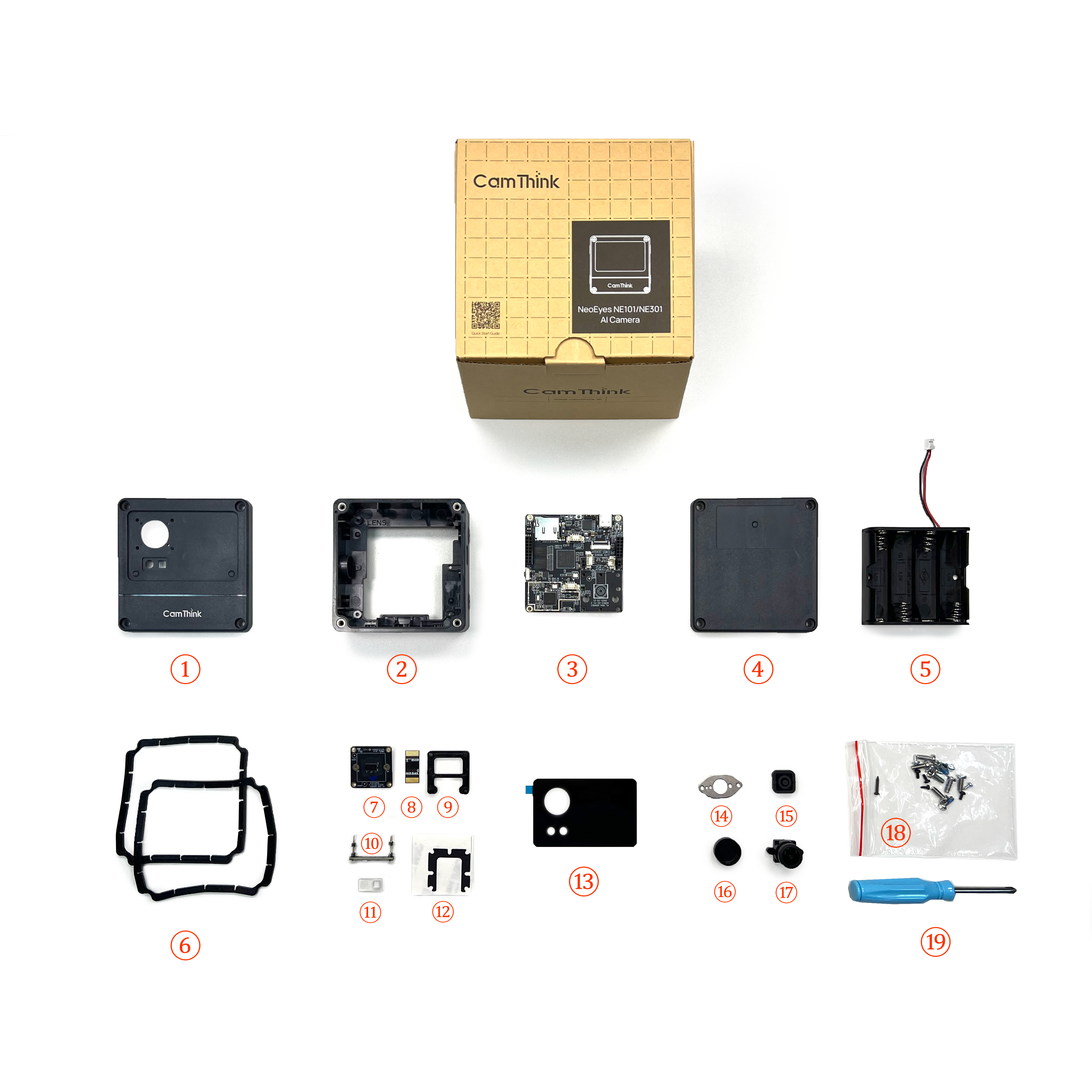
Component Parts:
① NE301_Top Cover ② NE301_Middle Frame ③ NE301_Mainboard ④ NE301_Bottom Cover ⑤ Battery Box ⑥ NE301_Sealing Ring ⑦ Sensor Mainboard ⑧ Sensor Auxiliary Board ⑨ M12 Lens Support Base ⑩ CV Light Board ⑪ X1_Lens ⑫ NE301_M12 Spacer (Dedicated for HFOV 137° lens module) ⑬ NE301_M12 Panel ⑭ NE301_Pressure Plate ⑮ NE301_Button ⑯ Lens Cap ⑰ Lens ⑱ Screw Package: Includes six types of screws, see parts list below for details ⑲ Screwdriver
Parts Checklist
After receiving the device, you can verify the components against the following checklist:
| Component Group | Part Name | Quantity | Notes |
|---|---|---|---|
| Housing | NE301_Top Cover | 1 | |
| NE301_Middle Frame | 1 | ||
| NE301_Bottom Cover | 1 | ||
| NE301_Button | 1 | ||
| NE301_Sealing Ring | 2 | One each for top and bottom covers | |
| NE301_Pressure Plate | 1 | Pressure plate for button patch | |
| NE301_M12 Panel | 1 | Panel for OS04C10 lens | |
| Boards | Mainboard (Wi-Fi) | 1 | Includes chip and other components |
| OS04C10 Camera Module | 1 | Includes Sensor board, auxiliary board (for connecting to mainboard), and lens | |
| CV Light Board | 1 | Connects to the mainboard | |
| Extension Board: Cat-1 (Optional) | 1 | ||
| Extension Board: POE (Optional) | 1 | ||
| Screws | Phillips Machine Screws (Thin Cylindrical Head, Original Color) | 8 | Screws for the back of the top and bottom covers |
| Phillips Self-tapping Screws (Pointed Tail, Carbon Steel, Galvanized) | 3 | Mainboard fixing screws for top-right, bottom-right, and bottom-left; 1.9*5mm | |
| Phillips Self-tapping Screws (Flat Tail, Carbon Steel, Black) | 3 | Two used for button pressure plate patch, one for fixing the bottom-right corner of the camera module | |
| Phillips Self-tapping Screws (Pointed Tail, Carbon Steel, Silver) | 2 | Screws for fixing battery compartment | |
| Phillips Self-tapping Screws (Pointed Tail, Blue-white Zinc or Black) | 1 | Mainboard fixing screw for top-left corner | |
| Phillips Self-tapping Screws (Pointed Tail, Carbon Steel, Galvanized) | 2 | For fixing the lens, 1.7*5mm | |
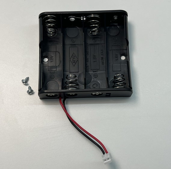
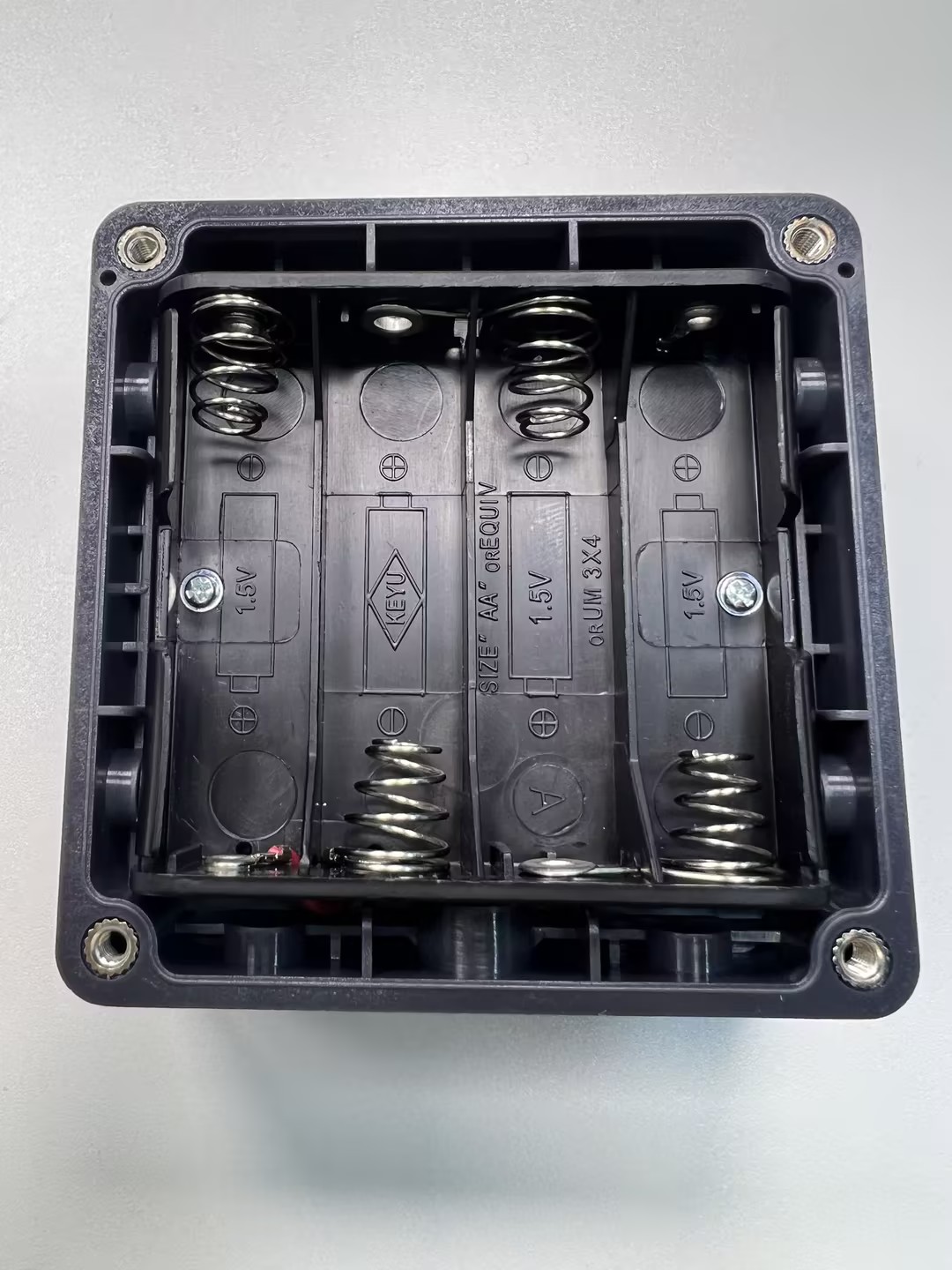
| Other Parts | Battery Box | 1 | Standard version defaults to battery power |
| NE301_M12 Spacer | 1 | Used for padding the bracket, dedicated for 137° lens module, not needed for 51°/88° modules | |
| M12 Lens Support Base | 1 | Supports the camera module | |
| X1_Lens | 1 | Frosted light board lens, placed between light board and panel |
Please Note: ① Batteries are not included in the shipment; you need to purchase four AA batteries separately. ② The standard configuration includes an OS04C10 module lens, with three FOV options available: 51°, 88°, 137°. ③ If you choose the 137° FOV lens, an additional spacer is included to support the lens; it is not required for other FOV modules.
Installation Steps
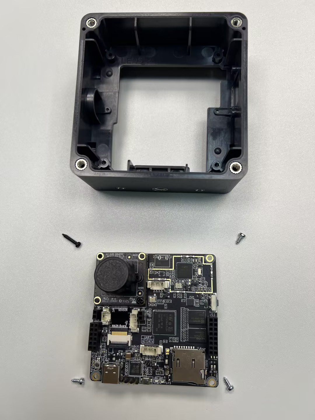
After checking the parts list and quantities, you can assemble the components individually to further confirm their completeness. This tutorial demonstrates the installation using the HFOV 137° as an example. Specifically, these are the top cover (four screws, lens protection foam, panel, X1 lens), middle frame (button pressure plate, button, two screws), bottom cover (four screws), battery box (requires four AA batteries), and mainboard (OS04C10 lens module, M12 lens support base, three short screws + one long screw), totaling five parts. The lens module includes the Sensor mainboard, auxiliary board, lens, lens fixing screws, M12 lens support base, and the spacer required for the HFOV 137° module.
The kit includes six types of screws, which differ slightly. Please distinguish them carefully:
- Phillips Machine Screws (Thin Cylindrical Head, Original Color)
- Phillips Self-tapping Screws (Pointed Tail, Carbon Steel, Silver)
- Phillips Self-tapping Screws (Pointed Tail, Carbon Steel, Galvanized, 1.9*5mm)
- Phillips Self-tapping Screws (Flat Tail, Carbon Steel, Black)
- Phillips Self-tapping Screws (Pointed Tail, Blue-white Zinc or Black)
- Phillips Self-tapping Screws (Pointed Tail, Carbon Steel, Black, 1.7*4mm)
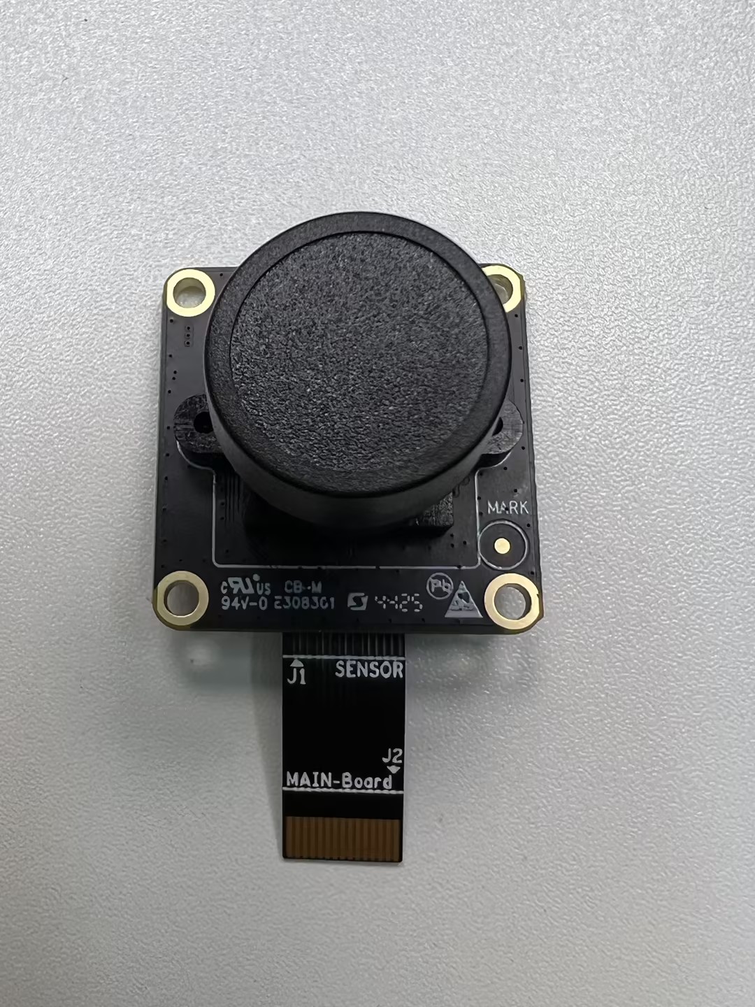
Step 1: Camera Module
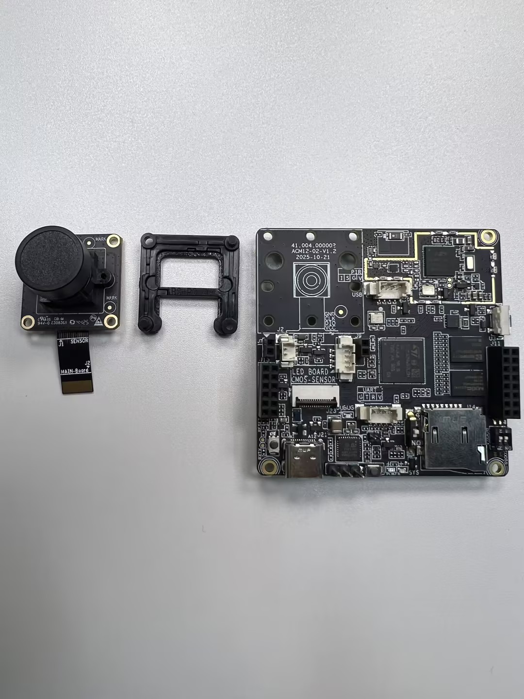
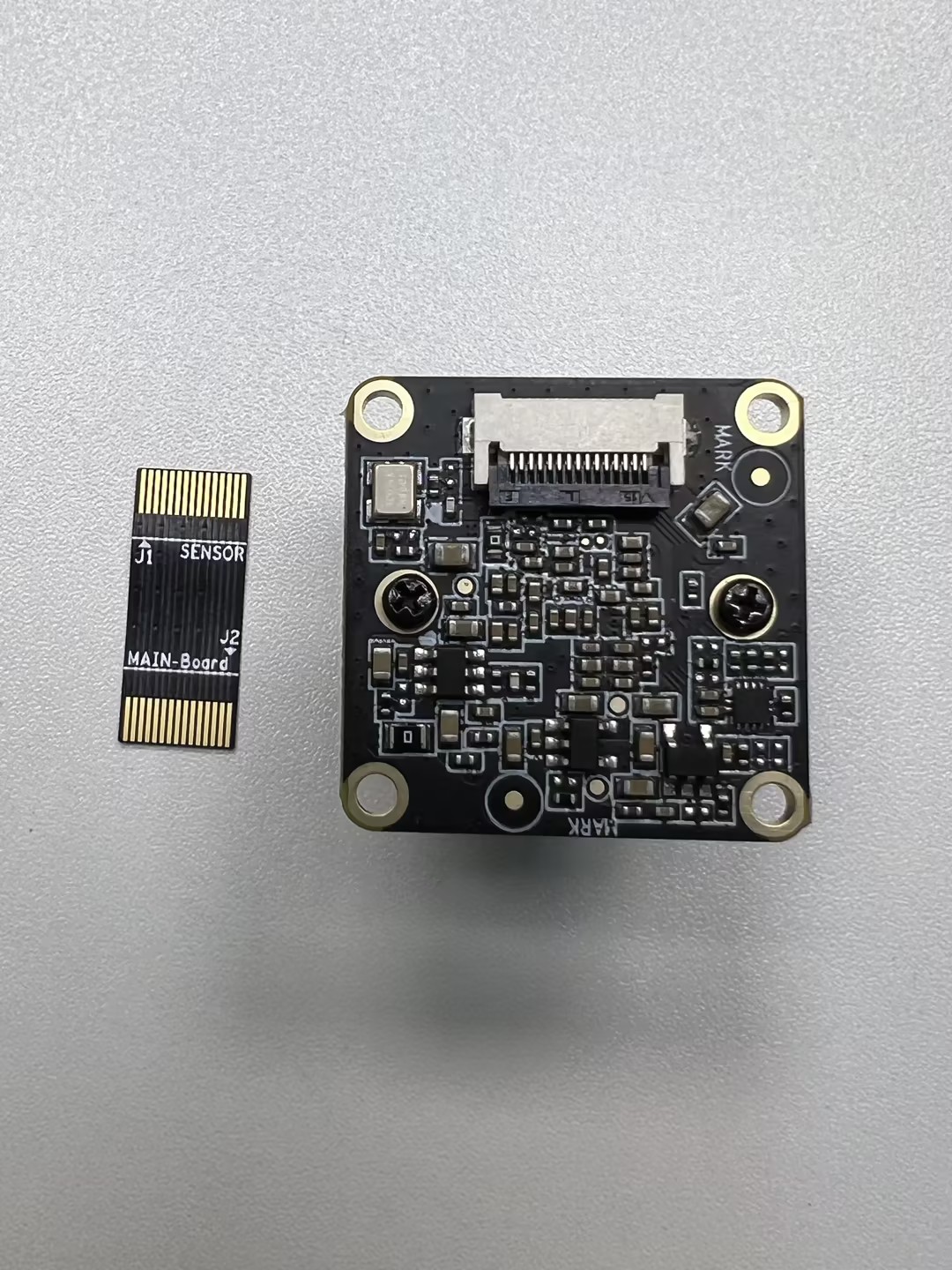
The overall effect is shown above, including the Sensor mainboard, auxiliary board, lens, lens fixing screws, M12 lens support base, the spacer needed for the HFOV 137° module, and the mainboard.
Objective: Secure the lens onto the Sensor board, tightening the lens module screws (Phillips self-tapping, pointed tail, carbon steel, galvanized) to ensure the lens module is firm. During installation, remember to remove the protective film from the Sensor board to ensure image clarity. Once removed, install the lens onto the Sensor board and tighten the screws.
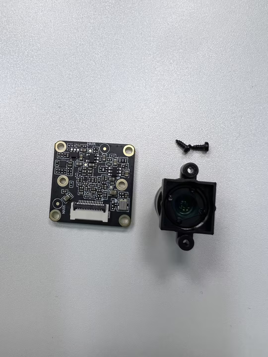
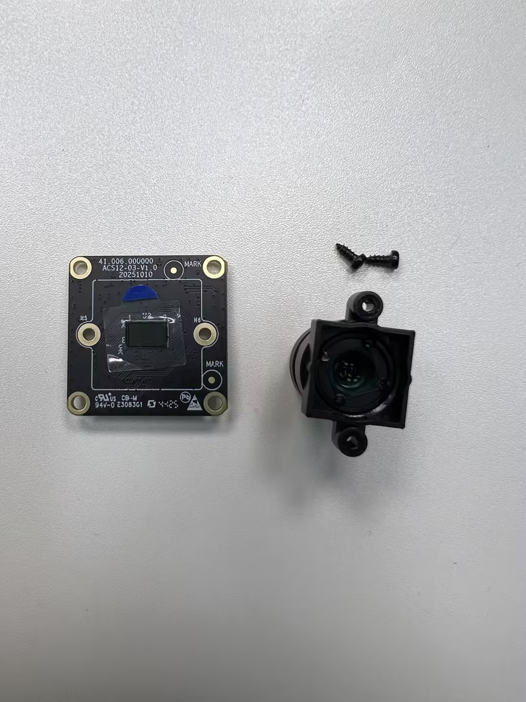
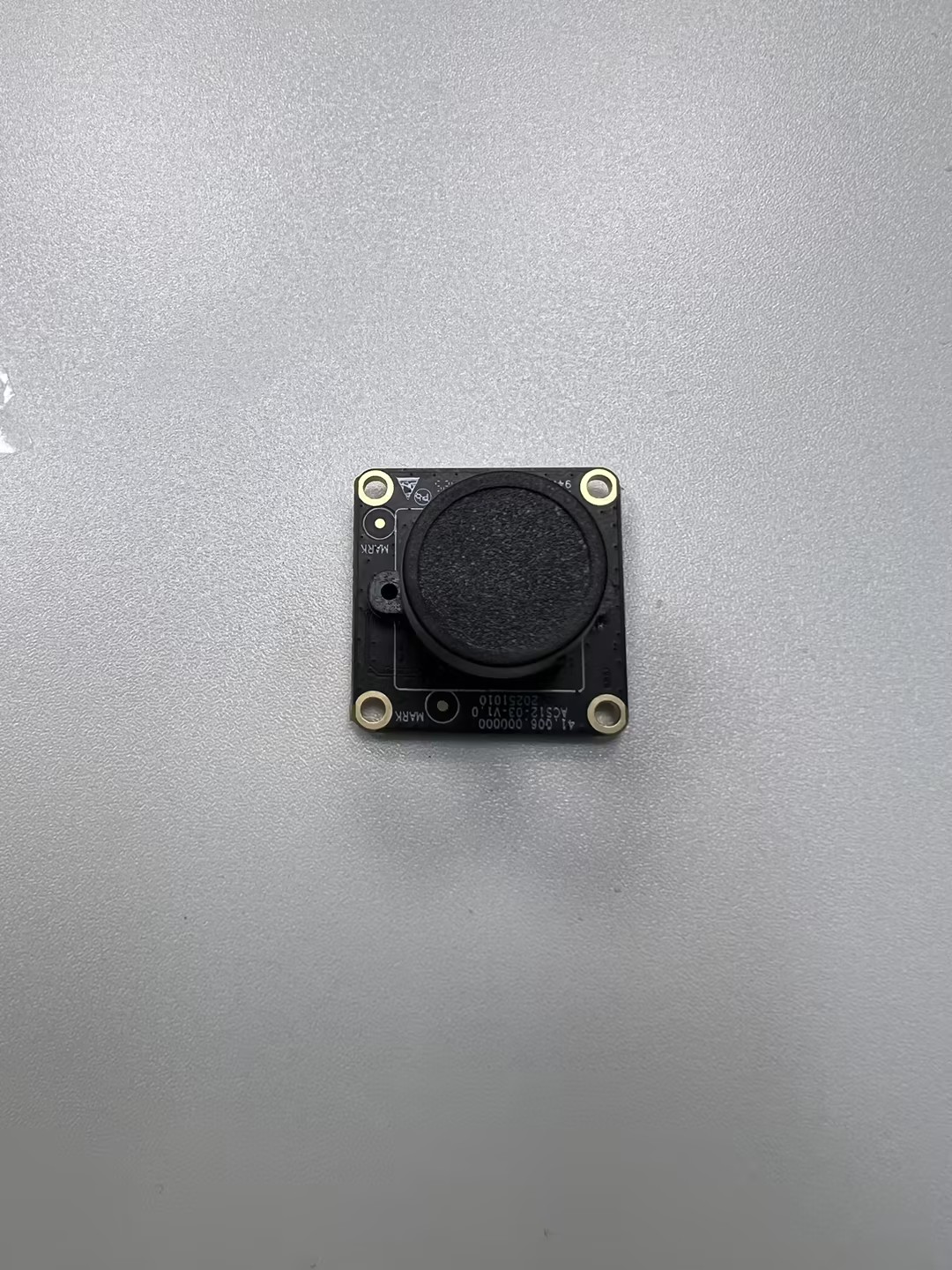
After installing the camera module, check if the lens is secure and the screws are tightened, then prepare the Sensor auxiliary board. The Sensor auxiliary board connects the Sensor board to the mainboard, ensuring stability.
Tips: Pay extra attention to the installation direction of the Sensor board. Incorrect orientation will prevent connection to the mainboard, causing the camera to malfunction.
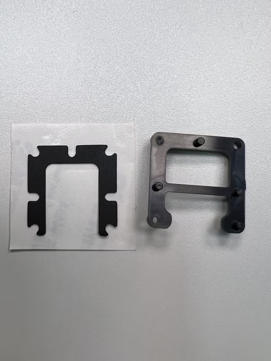
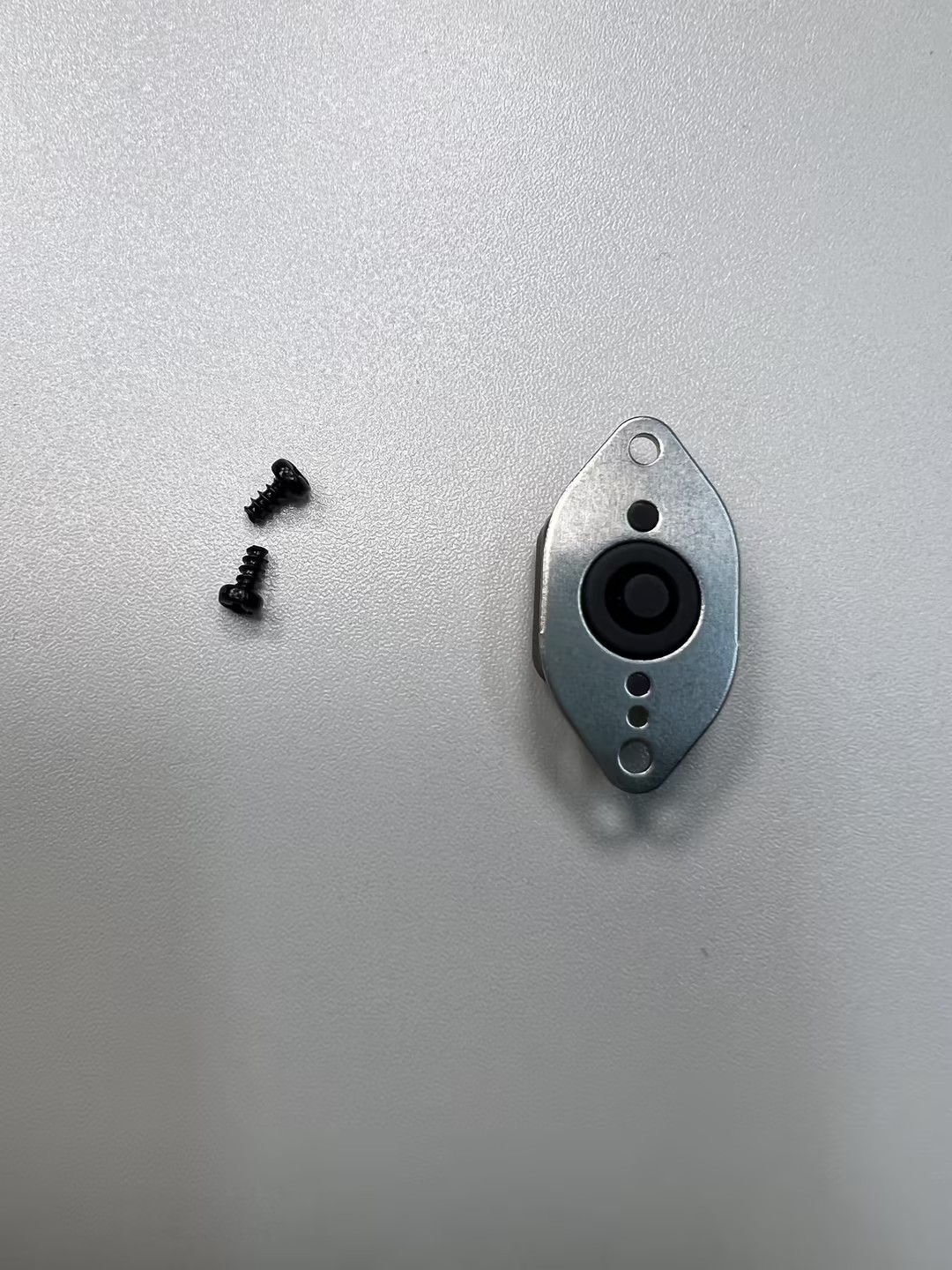
If your lens module is 137° FOV, attach the NE301_M12 spacer to the back of the lens module as shown below:
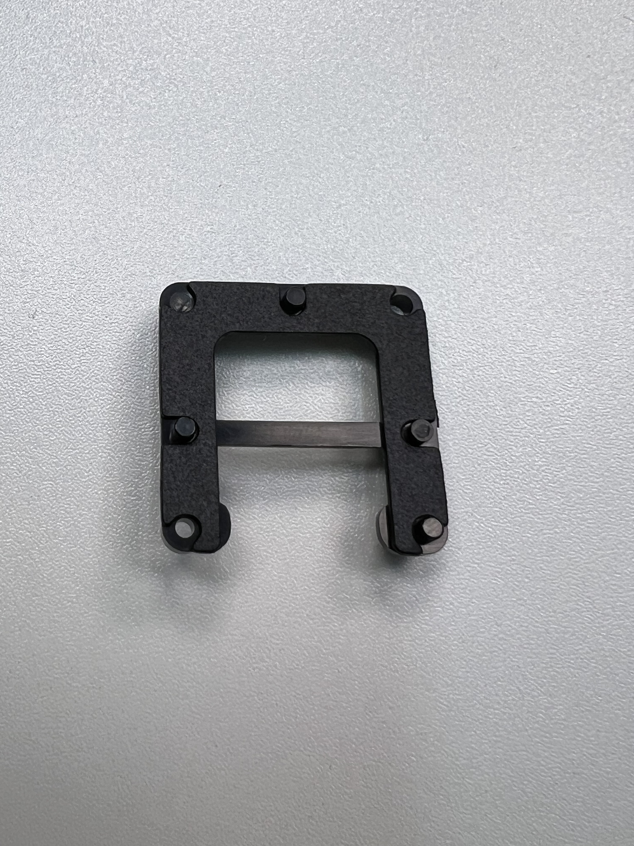
The fully assembled lens module is shown below. You will need to remove the protective lens cap before mounting it to the mainboard.
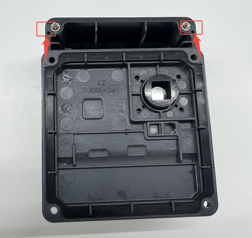
Step 2: Top Cover Assembly
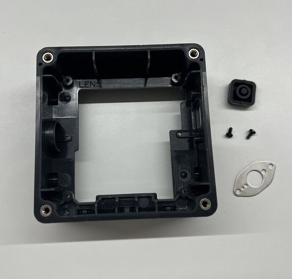
Once the camera module is ready, you can assemble the housing. Below is a diagram of the housing parts.
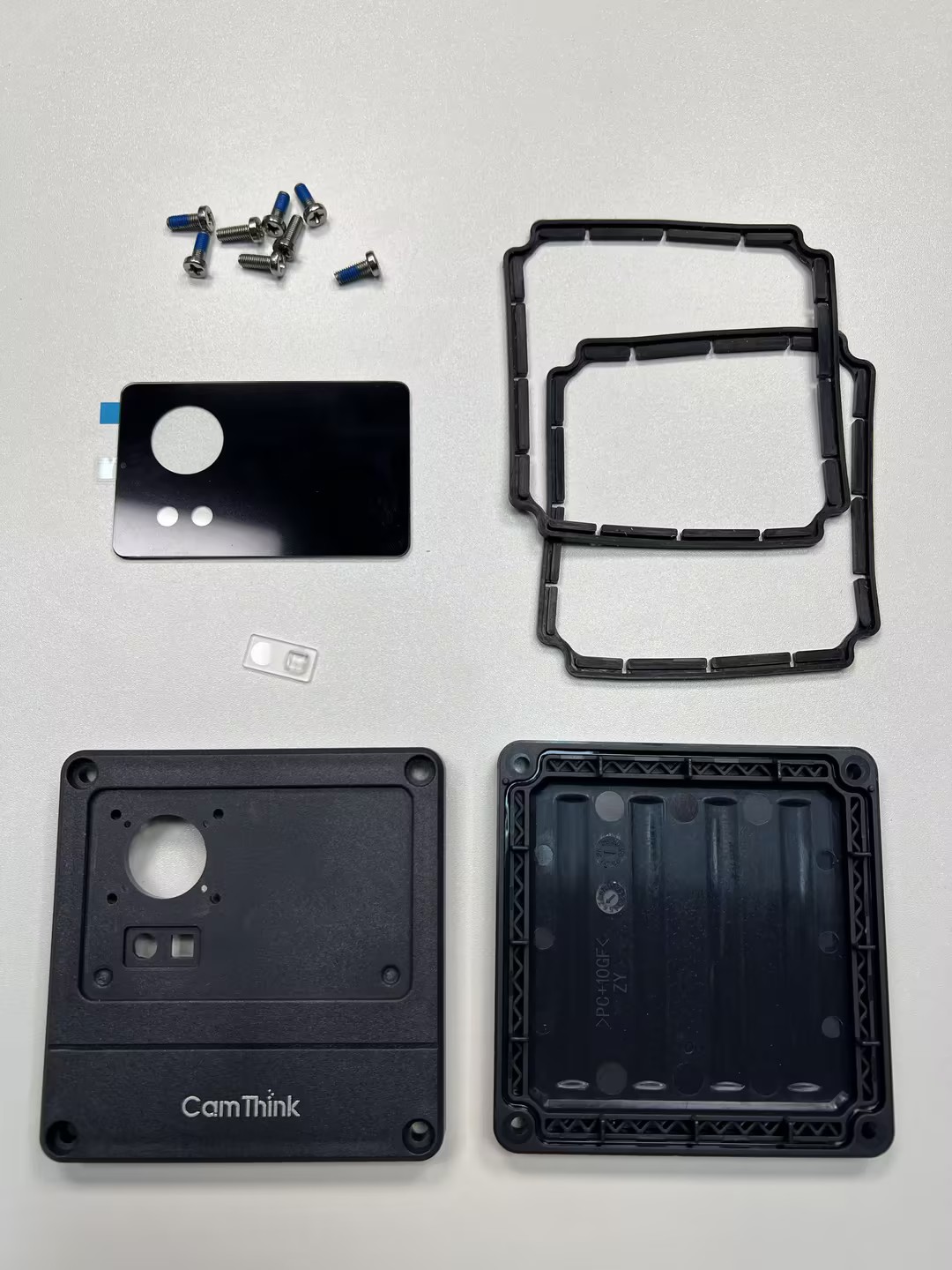
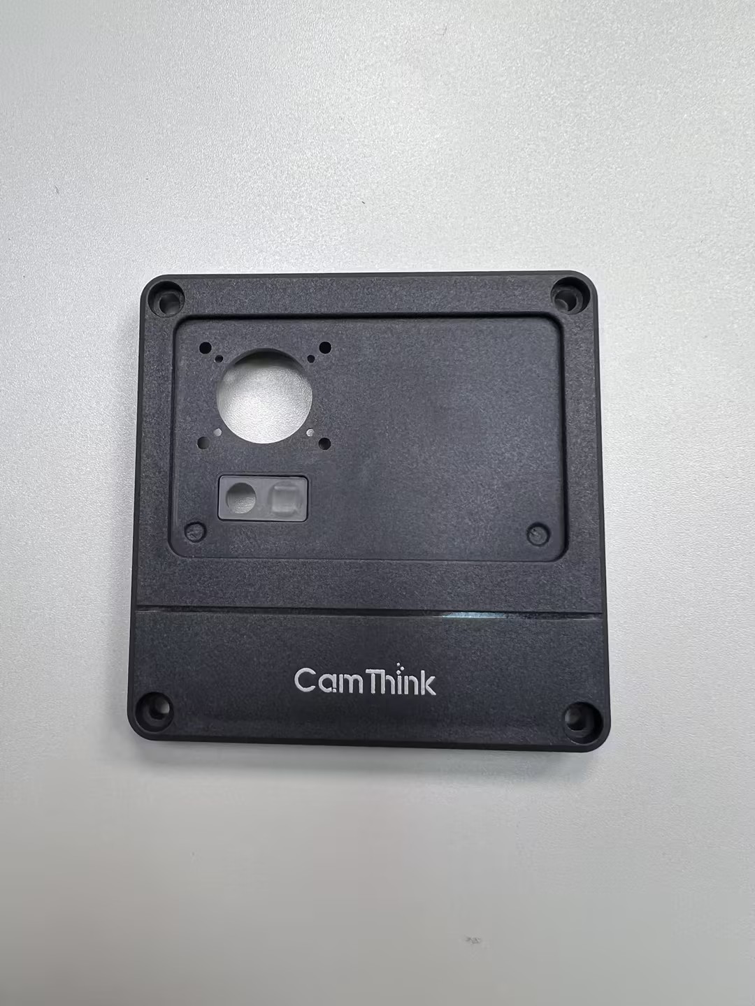
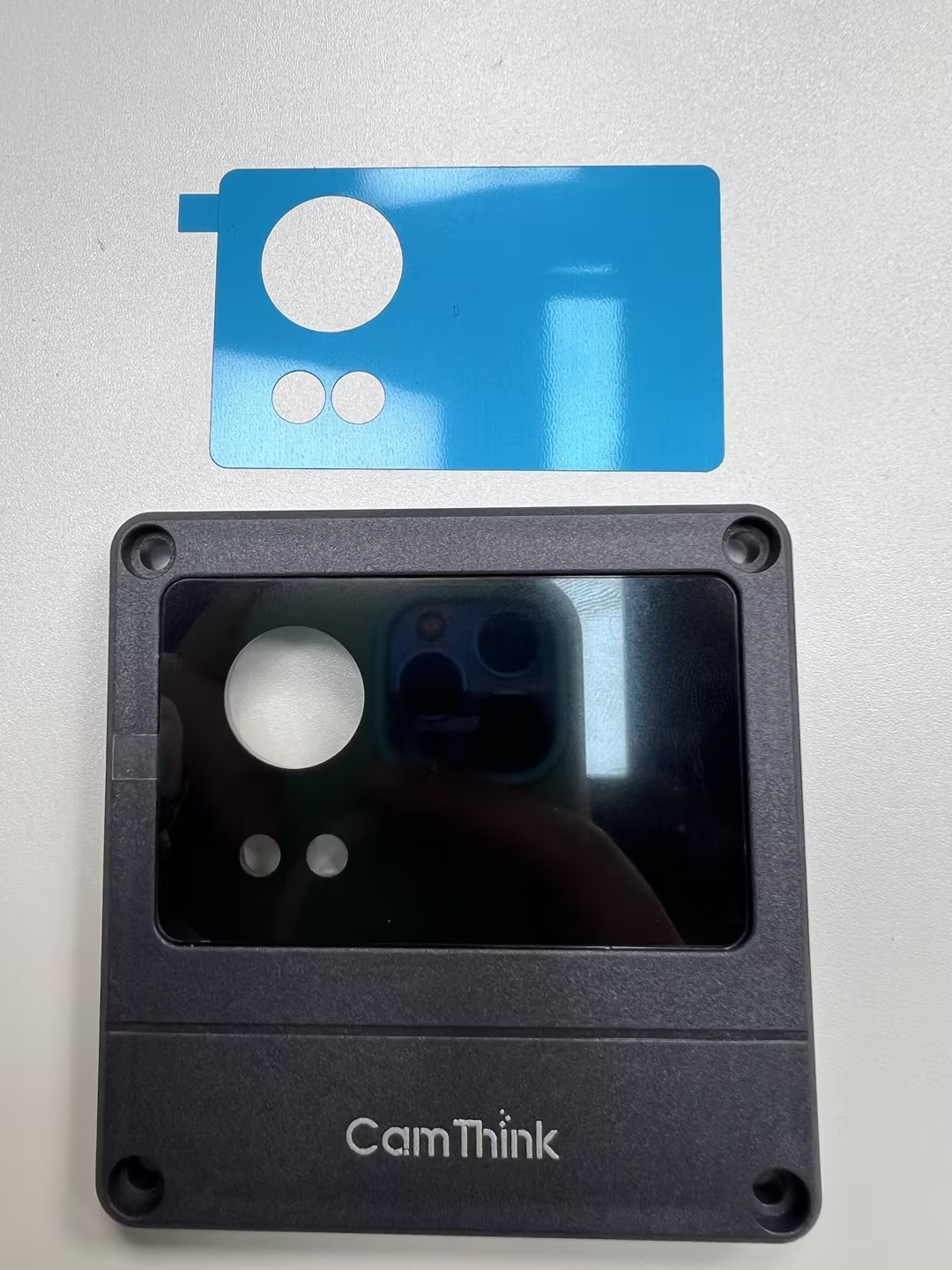
Start with the top cover, which involves the camera panel. Top cover assembly: Includes internal M12 panel, X1 lens (white, for the light board), three short screws for fixing to the middle frame, one long screw, and the top cover sealing ring.
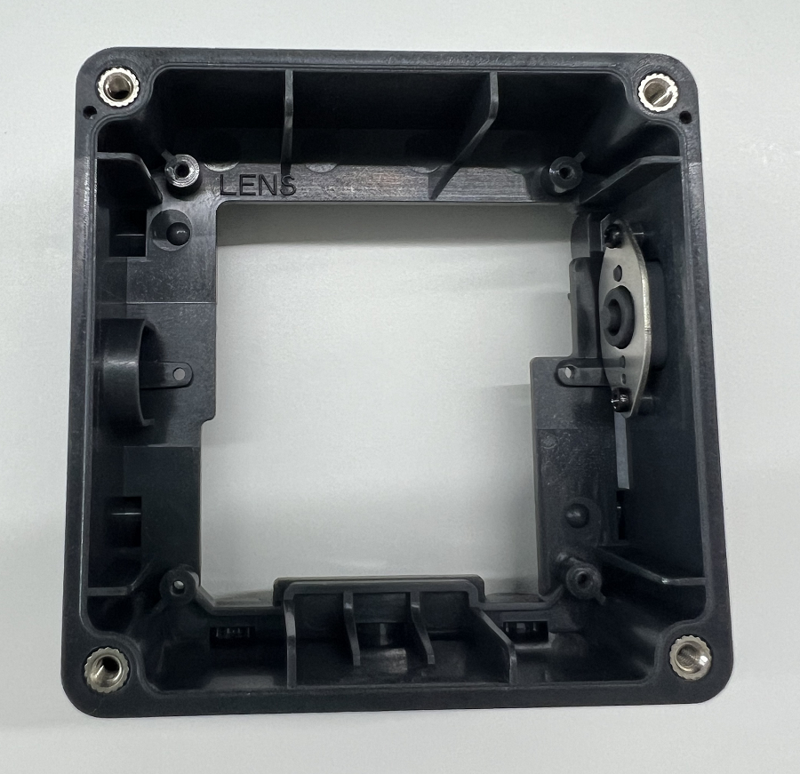
First, place the sealing ring in the groove on the inside of the top cover (note the installation direction), then place the white transparent X1 lens into the two holes (one round, one square). Peel off the adhesive from the back of the panel and stick it into the groove of the top cover, ensuring hole alignment. This will also secure the X1 lens. Finally, remove the protective film from the panel before use to ensure clarity.
Tips: Ensure the white X1 lens is correctly placed before sticking the glass panel.
Step 3: Middle Frame Assembly
Middle frame parts: NE301_Button, NE301_Pressure Plate, two Phillips self-tapping screws (flat tail, carbon steel, black).
As shown above, check the components and align the holes. Install the button on the side of the middle frame with the camera icon facing outward. Place the pressure plate over the button, passing through the cylinders on both sides, and secure with two screws. Tighten these screws firmly to prevent button loosening or misalignment. If you have experience with the NE101, this will be even easier!
Tips: It is best to install the buttons before mounting the mainboard to avoid misalignment.
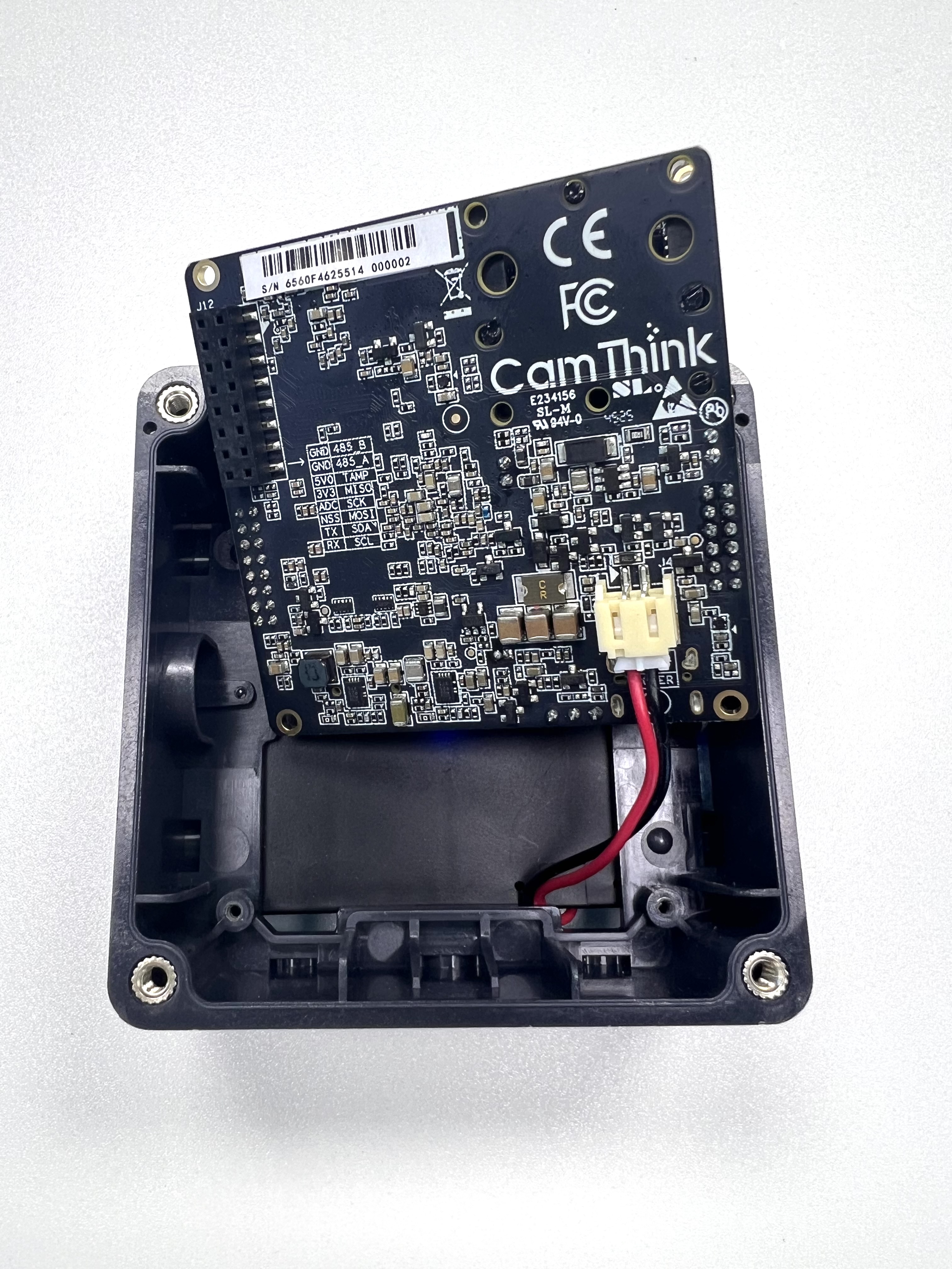
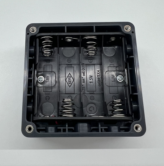
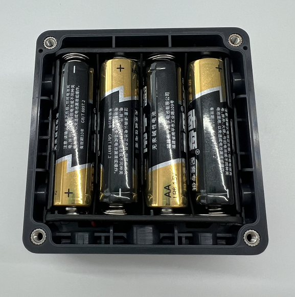
Step 4: Battery Box Assembly
Battery box assembly: The standard version is battery-powered. It is fixed to the middle frame using two screws through the holes inside the battery box. The connection wire attaches to the power interface on the back of the mainboard.
Step 5: Bottom Cover Assembly
Bottom cover assembly: Place the sealing ring in the groove on the inside of the bottom cover and prepare the four screws.
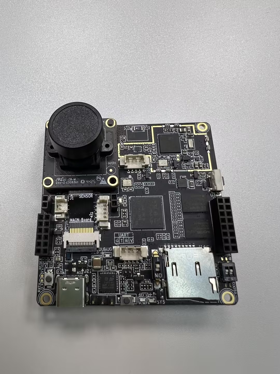
Step 6: Mainboard Assembly
Mainboard parts: Includes M12 lens support base, OS04C10 lens module (assembled previously), CV light board, and four screws (three short Phillips self-tapping galvanized + one long Phillips self-tapping blue-white zinc or black) for fixing to the middle frame.
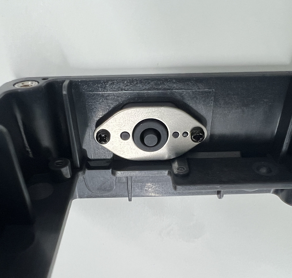
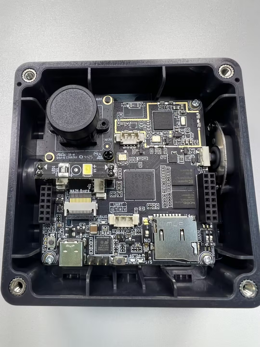
Connect the Sensor auxiliary board of the lens module into the mainboard clip. This clip is a flip-type; lift to insert and press down to lock the cable. Finally, plug the CV light board pins into the mainboard below the camera module—the round light sensor on the left and the square fill light on the right. Once secure, remove the protective cap from the lens.
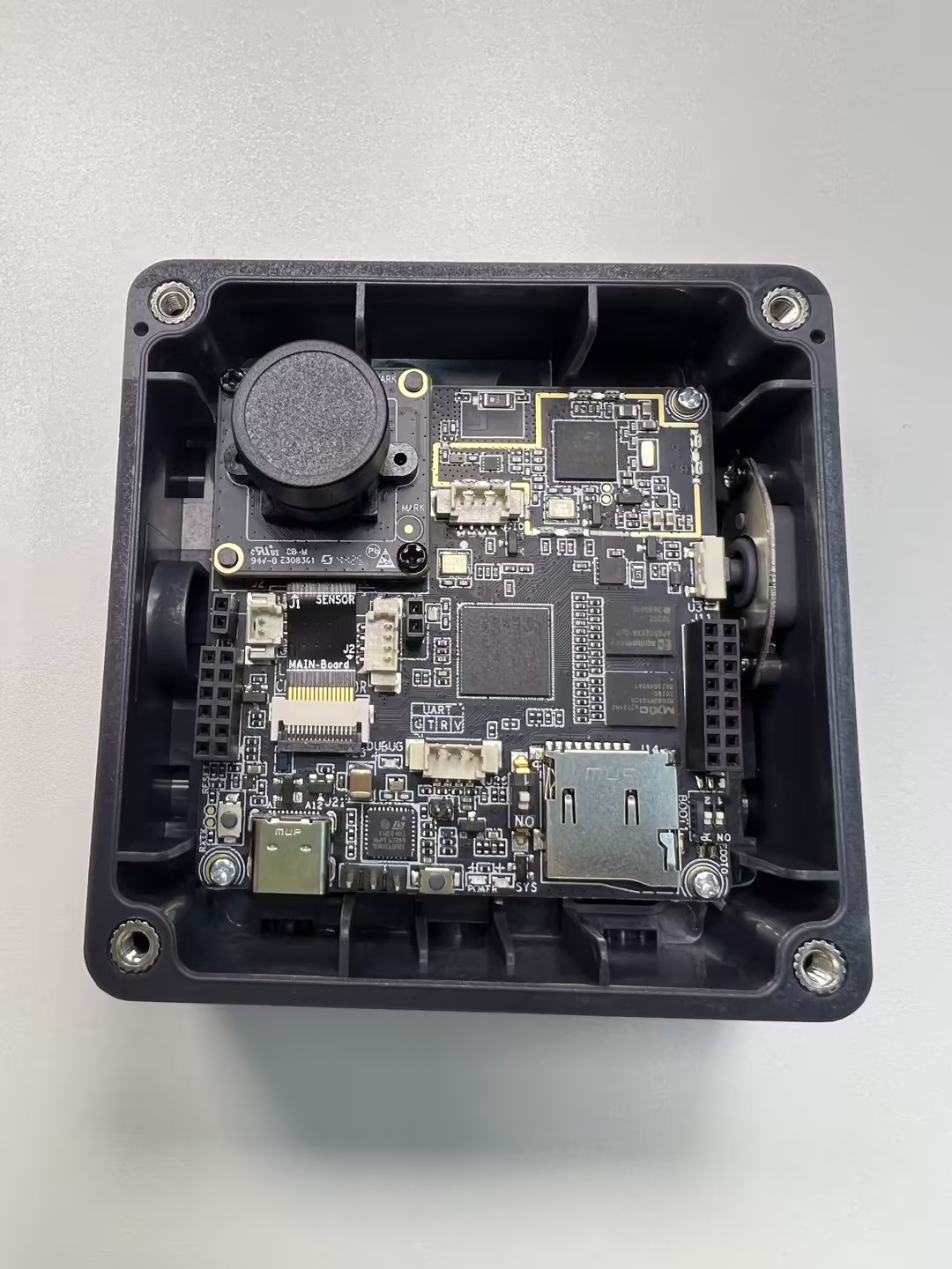
The mainboard assembly is shown below:
Note: ① For development and debugging, ensuring the lens is usable is sufficient. ② for immediate deployment, it is recommended to secure the camera module and mainboard connection using hot-melt adhesive or soldering.
Choose the most suitable lens module based on your deployment height, space, and target. You can upgrade visual performance at a low cost by simply swapping the lens module without changing the mainboard. Supported module specifications:
| Type | Model | FOV | Focus Distance | Scenario |
|---|---|---|---|---|
| Camera Module | OS04C10 | 51° | 4m | Long-distance capture |
| Camera Module | OS04C10 | 88° | 3m | Medium-distance capture |
| Camera Module | OS04C10 | 137° | 2m | Close-range wide-angle capture |
Tips: You can manually adjust the lens focus during debugging.
Step 7: Fixing the Battery Box
After securing the mainboard to the middle frame, connect the battery box wire to the power interface on the back of the mainboard, as shown below. Secure the battery box to the middle frame with two screws (pointed tail, carbon steel, silver) through the internal holes, then insert the batteries.
The middle frame, mainboard, and battery components are now fully secured.
Step 8: Securing the Covers
Finally, align the top and bottom covers with the middle frame holes and secure each with four screws to complete the assembly.
Important Detail: Ensure the raised circular parts of the covers align with the recessed parts of the middle frame. Otherwise, gaps will remain.
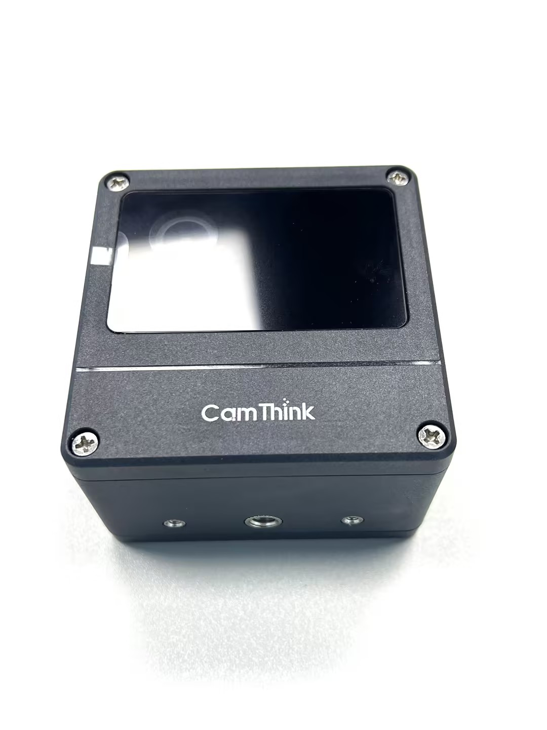
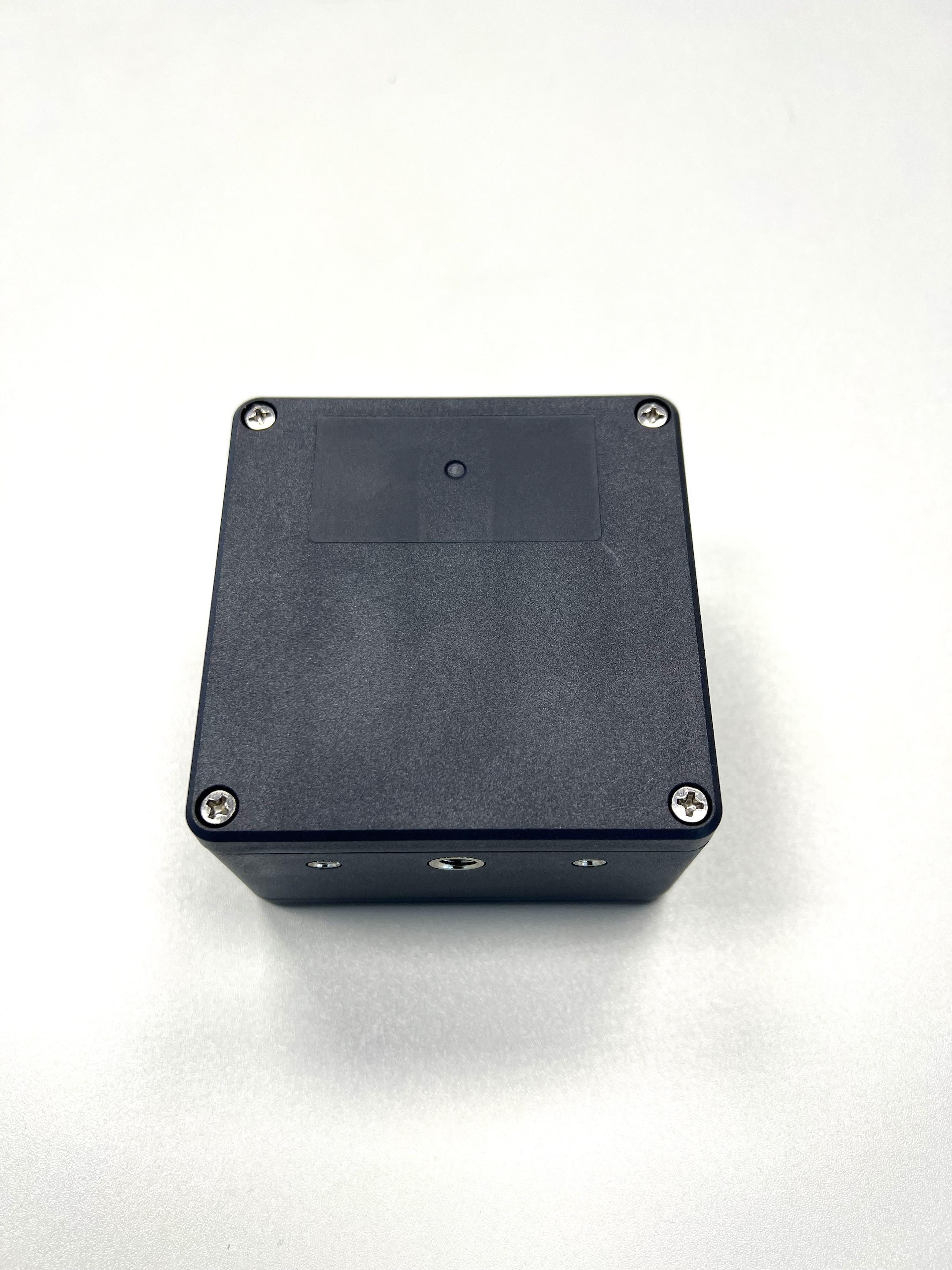
Your NE301 AI Camera Developer Kit is now fully assembled. For usage and deployment, see — Quick Start.
For questions or suggestions, join our community on Discord or provide feedback on GitHub Issues — Discord.