Alarm Application Trigger Guide
Application Description
You want to trigger the NE101 to capture an image via an external alarm or manual trigger by connecting an Alarm to the NE101.
In practice, you might encounter the following issue: You have correctly enabled Enable Alarm-In Capture (enable alarm input capture) in the Web interface or other configuration tools, and connected a physical alarm button (such as a dry contact switch) to the Alarm Interface on the motherboard. However, when the button is pressed, the camera cannot be woken up, and no photo capture or alarm reporting is triggered.
Root Cause
This issue is mainly caused by a resource reuse conflict in the NE101 hardware design. It is not a software bug but a result of limited hardware resources. The default design supports PIR but not Alarm, though Alarm support can be achieved manually. The specific reasons are as follows:
-
Firmware/IO Resource Conflict: In the NE101 firmware source code
main/sleep.handmain/misc.h, both the PIR sensor interrupt signalPIR_INTDOUT_IOand the Alarm input signalALARM_IN_IOare defined as the same pin: GPIO 2.Reference code:
// Related definitions in main/sleep.h & main/pir.h & main/misc.h
#define PIR_INTDOUT_IO      (2)
#define ALARM_IN_IO (2) -
Default Hardware Circuit Configuration: The current version of the NE101 hardware motherboard is configured by default to support PIR sensors. To ensure signal quality, GPIO 2 is physically connected to the PIR Interface by default. The path from the independent Alarm Interface to GPIO 2 is disconnected at the factory (missing a key connecting resistor). Therefore, even if the Alarm function is enabled in the software, GPIO 2 is actually in a floating state or only controlled by internal pull-up, and cannot sense level changes at the Alarm Interface.
Solutions
There are two solutions to this problem. It is recommended to choose based on your actual hands-on ability and application scenario:
Solution 1: Modify Connection (Recommended)
Directly use the PIR Interface, which is already connected, to access the Alarm button. This is the simplest method and does not damage the motherboard.
Steps:
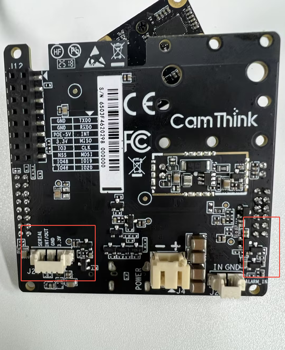
- Locate the 4-Pin PIR Interface on the motherboard.
- Prepare the connection wires for the Alarm button (usually 2 wires: Signal and Ground).
- Connect the Alarm button to the PIR interface, using only the 1st and 3rd pins from the left:
- Signal (GPIO 2)
- GND (Ground)
- Leave the other 2 pins (VCC, etc.) unconnected.
Principle:
Since the Signal pin of the PIR interface is physically connected to GPIO 2, connecting a dry contact button between Signal and GND works effectively. When the button is pressed, the Signal is pulled low (to GND), which matches the ALARM_IN_ACTIVE (0) trigger logic in the firmware, thus successfully triggering the alarm.
Solution 2: Modify Hardware
If you must use the independent Alarm Interface, a minor hardware modification to the motherboard is required.
Steps:
- Locate the right side area of the motherboard.
- Find the empty pad position (associated resistor position) related to the Alarm Interface path.
- Solder a 0Ω resistor (or short it directly with tin) to connect the Alarm Interface to GPIO 2.
Note:
- This operation requires soldering tools and some hardware experience.
- Warning: After modification, GPIO 2 will be connected to both the PIR Interface and the Alarm Interface. Ensure that you do not connect a PIR sensor and an Alarm button simultaneously; otherwise, their signals will interfere with each other, potentially causing short circuits or false triggers.
Firmware Configuration Confirmation
Regardless of which hardware solution you use, please ensure the firmware configuration matches the dry contact mode (default configuration):
- PIR_ENABLE should be
0(disable PIR driver logic, wake up via general GPIO interrupt). - Enable Alarm-In Capture must be enabled.
In the logic of main/sleep.c, when PIR_ENABLE is 0 and Alarm is enabled, GPIO 2 will be configured as Internal Pull-up. Pressing the button pulls the level low to wake up the device.
Reference code:
// main/sleep.c
#if PIR_ENABLE
    // ... PIR logic ...
#else
    if(capture.bAlarmInCap == true){
        rtc_gpio_pullup_en(ALARMIN_WAKEUP_PIN); // Enable pull-up
        rtc_gpio_pulldown_dis(ALARMIN_WAKEUP_PIN);
        esp_sleep_enable_ext1_wakeup(BIT64(ALARMIN_WAKEUP_PIN), ALARMIN_WAKEUP_LEVEL); // Wake up on low level
    }
#endif