Hardware Connection
This page identifies the external, serial, and programming interfaces on the Interface Board. Complete first assembly, installation, power-up, and sign-in with the Quick Guide. Disconnect device power before connecting MicroSD or ST-LINK, or changing a programming switch. The silk-screen label on the delivered board is authoritative.
External interfaces
| Connection | Use | Success check |
|---|---|---|
| USB Type-C | Continuous 5 V device power, or a delivery-compatible external battery pack connected through USB Type-C; also provides the supported USB connection for the delivered configuration | Device starts and the Web console becomes reachable |
| MicroSD | Local storage for the configured capture or record workflow | Storage Management reports the card state after startup |
| Trigger / Reset | Physical input or recovery control provided by the delivered hardware and firmware | Use only the function exposed by the delivered device; do not infer signal levels from this guide |
| External SMA antenna | Wireless connection for an external-antenna configuration | Antenna is firmly fitted, has clearance from metal, and wireless connectivity can be tested |
The Interface Board provides N6_UART for the STM32N6 serial console. Use the matching adapter and serial procedure; the source README lists 921600 baud. Do not infer electrical levels or pin assignments from this guide.
Identify programming interfaces
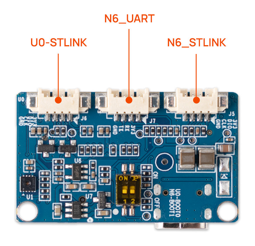
| Board label | Physical target |
|---|---|
U0-STLINK | STM32U0 SWD programming and debugging interface |
N6_UART | STM32N6 serial-console interface |
N6_STLINK | STM32N6 SWD programming and debugging interface |
N6-BOOT | STM32N6 boot-mode switch |
U0-BOOT | STM32U0 boot-mode switch |
This guide identifies the connectors and switches only. Target selection, switch sequence, ST-LINK-to-PC connection, and flashing commands are in Build, Flash and Update.