Quick Guide
Complete this first-use path: assemble and power the device → sign in to the Web console → confirm the preview → upload a model and validate an image → run one trigger and confirm a Records entry. Field explanations and troubleshooting are in the User Guide.
1. Prepare the hardware
Prepare the NE302 Main Board, Interface Board, camera assembly, the antenna for the delivered SKU, and either a continuous USB Type-C (5 V) supply or a delivery-compatible external battery pack that powers the device through USB Type-C. Add a MicroSD card when capture records must be saved, and use a computer that can reach the device network.
This procedure applies to the complete NE302 device (Main Board + Interface Board). The Main Board can also be used for a custom Main-Board-only integration and uses DC power according to the delivery record; MicroSD steps for the Interface Board do not apply.
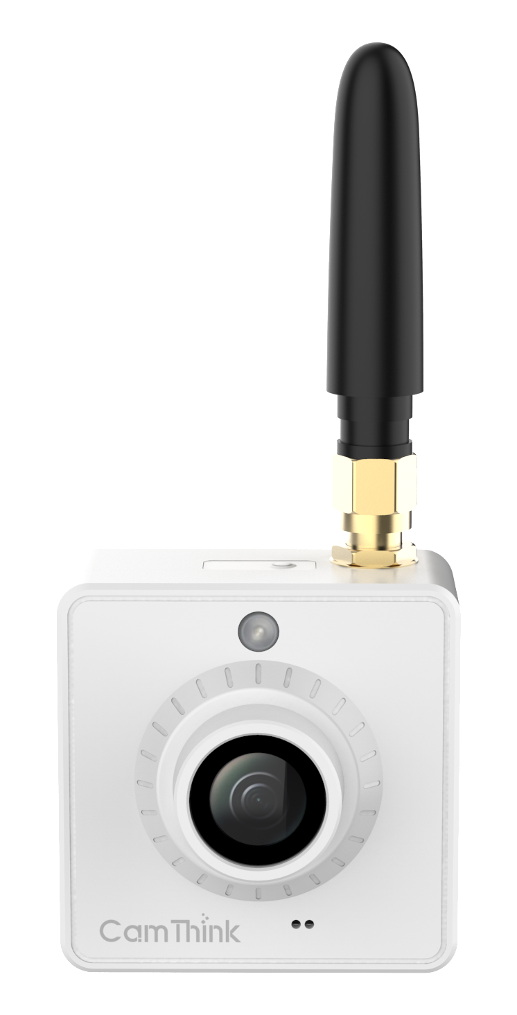
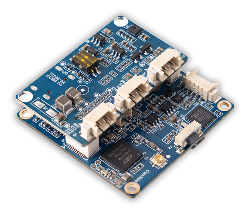
The left image shows the finished product; the right image shows the board assembly. Follow the delivery hardware record for power, antenna and board revision.
2. Assemble and power the device
- With power disconnected, mate the Main Board and Interface Board in the keyed connector direction. Do not force or angle the connector.
- Attach the antenna for the delivered SKU. Insert a MicroSD card when local storage is required.
- Mount the device for the site field of view. The standard enclosure supports a rear magnetic mount or double-sided adhesive; use the method below.
- Connect USB Type-C to a continuous power supply or compatible external battery pack according to the delivery record, then wait for startup.
Mounting methods
This section applies to the standard two-board device with its enclosure. Mount with power disconnected, and leave a clear lens view plus access for power, antenna and maintenance. A Main Board-only configuration must use the delivered information for DC power and mechanical integration; the standard enclosure mounting methods may not apply.
Rear magnetic mount
- Choose a flat mounting surface that the magnet can hold, and confirm that the position covers the intended field of view.
- Bring the rear magnetic surface fully into contact with the mounting surface.
- Gently push the device to confirm that it does not slide or detach. Connect the antenna and power cable afterwards, without allowing either cable to pull on the device.
Rear double-sided adhesive
- Choose a flat, dry mounting surface and clean both it and the rear of the device.
- Remove the adhesive liner, align the device with the target position, then press the rear evenly into place.
- Confirm that the device is fixed before connecting the antenna and power cable, without allowing either cable to pull on the device.
After mounting, confirm that the lens view is unobstructed and that the external antenna is fitted and clear of large metal obstructions. Power on, then confirm under Feature Debugging that the preview orientation and coverage match the site target. If the image is unsuitable, disconnect power, adjust the mounting position, then check the preview again.
If the device does not start, disconnect power, check the board connection, camera connection and power, then power it on again.
3. Sign in to the Web console
- Connect the computer to the network specified by the delivery record.
- Open the device address in a browser. Some test devices use
http://192.168.10.10/; the actual address follows the device configuration. - Sign in with the credentials delivered with the device. If the page requires a login-password change, complete it and sign in again with the new password.
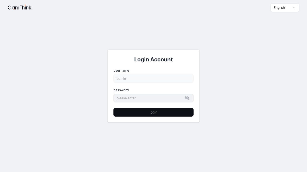
The access check passes when the console opens and displays the function navigation.
4. Confirm the live preview
- Open Feature Debugging.
- Wait for the preview area and Camera Settings to finish loading.
- Confirm that the preview continuously shows an image and that its orientation matches the installation.
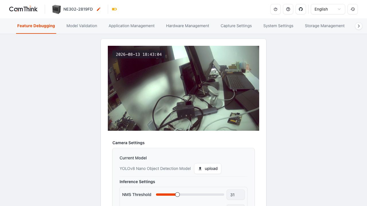
If there is no image, check the camera connection and power first, then see Capture and Storage.
5. Upload a model and validate an image
- Download a
.binmodel package compatible with the device from CamThink Developer Center → Models. - In Feature Debugging → Camera Settings, select upload in the Current Model area and wait for the model to load.
- Open Model Validation and upload one fixed test image.
- Wait for the result area to update and confirm that the page returned an inference result.
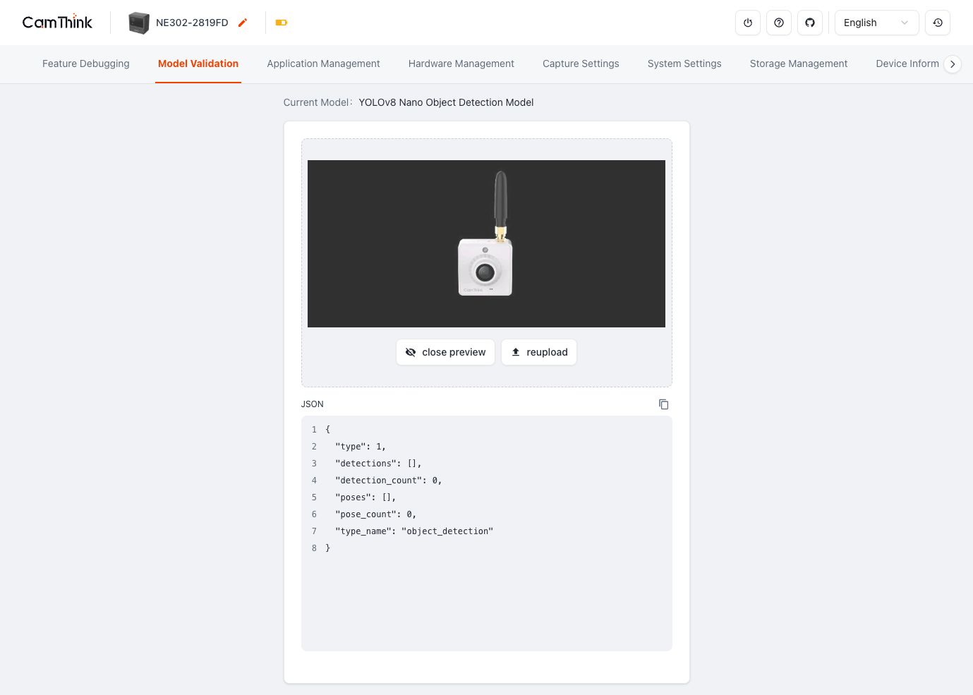
See AI Model Validation for model formats, parameters and result interpretation.
6. Run one trigger and confirm Records
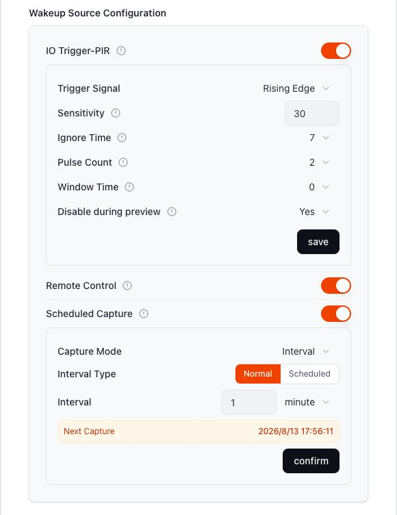
- In Feature Debugging → Wakeup Source Configuration, enable one test source only and save the setting.
- Use that source to trigger the device once.
- Open Capture Settings → Records and find the matching entry by trigger time.
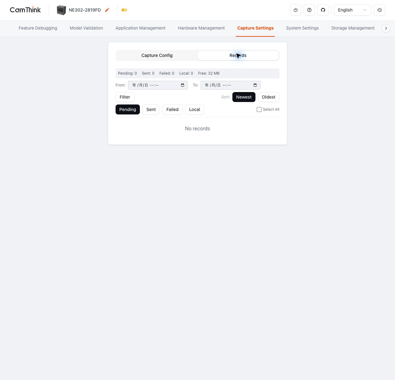
The first capture check passes when Records contains the entry with the matching time.
7. Next steps
- Capture and Storage: configure capture, storage and triggers.
- Data Transmission: configure MQTT/MQTTS, Webhook and media-stream delivery.
- AI Model Validation: manage models and inference validation.
- System Maintenance: manage network, firmware, storage and device information.
- Hardware Guide: identify boards, interfaces and hardware revision.
- Software Guide: build, flash and maintain the source project.