Build, Flash and Update
This page covers source builds, hardware flashing and update package preparation for NE302. Use only the interface for the target MCU: STM32N6 uses N6-STLINK, while STM32U0 / WakeCore uses U0-STLINK.
Complete Environment setup first, then confirm the target device, source version and component to be flashed.
1. Identify the flashing target
| Target | MCU | Device interface | Boot switch | Main command |
|---|---|---|---|---|
| FSBL, App, Web, Model, WiFi | STM32N6 | N6-STLINK | N6-BOOT | make flash-<component> or make flash |
| WakeCore | STM32U0 | U0-STLINK | U0-BOOT | make flash-wakecore |
N6 and U0 are independent flashing paths. Connect only one path at a time. Do not use N6-STLINK for WakeCore or place a WakeCore file in the App, Model or Web update entry.
2. Build, sign and package
Run these commands from the source root:
make info
make                 # Build FSBL, App, Web, Model and WakeCore
make app             # Build App only
make web             # Build Web only
make model           # Build Model only
make wifi-image      # Build the WiFi image
The build and deployment steps differ by component:
| Component | Compile | Sign | Package | Flash |
|---|---|---|---|---|
| FSBL | make fsbl | make sign-fsbl | make pkg-fsbl for OTA | make flash-fsbl |
| App | make app | make sign-app | make pkg-app | make flash-app |
| Web | make web | Not required | make pkg-web | make flash-web |
| Model | make model | Not required | make pkg-model | make flash-model |
| WiFi | make wifi-image | Not required | make pkg-wifi | make flash-wifi |
| WakeCore | make wakecore | Not required | Not on the normal OTA path | make flash-wakecore |
The signed FSBL .bin can be flashed directly. App must be signed and then packaged. Web and Model do not require signing, but both flashing and OTA use packaged files. To create the complete OTA package set:
make sign
make pkg
WakeCore is flashed through its own build flow and is not included in the normal make pkg set.
Model runtime variant
The source supports 2.2, 3.0 and 4.0, with 4.0 as the default. When rebuilding a model, STEDGEAI_VARIANT, STEDGEAI_CORE_DIR, the App runtime and the Model package must use the same variant:
make model STEDGEAI_VARIANT=4.0
If the variants differ, return to Environment setup, correct the tools and rebuild before flashing.
3. Flash STM32N6
STM32N6 covers FSBL, App, Web, Model and WiFi. The sequence is fixed: set the switch → connect the hardware → power or reset → run the command on the PC → return the switch to run mode.
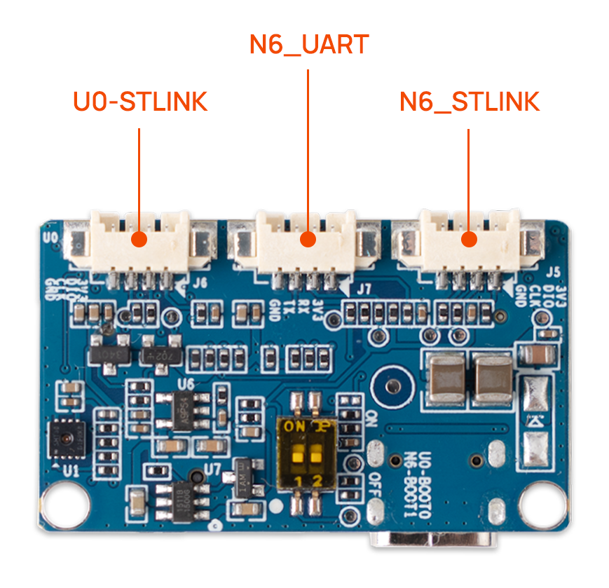
The image below labels the programming and serial interfaces on the actual Interface Board: N6_STLINK is for STM32N6, U0-STLINK is for STM32U0, and the middle N6_UART connector is serial, not an ST-LINK flashing interface.
Hardware connection
- Power off the device.
- Set the interface-board
N6-BOOTswitch toward the printed ON side. - Connect: device
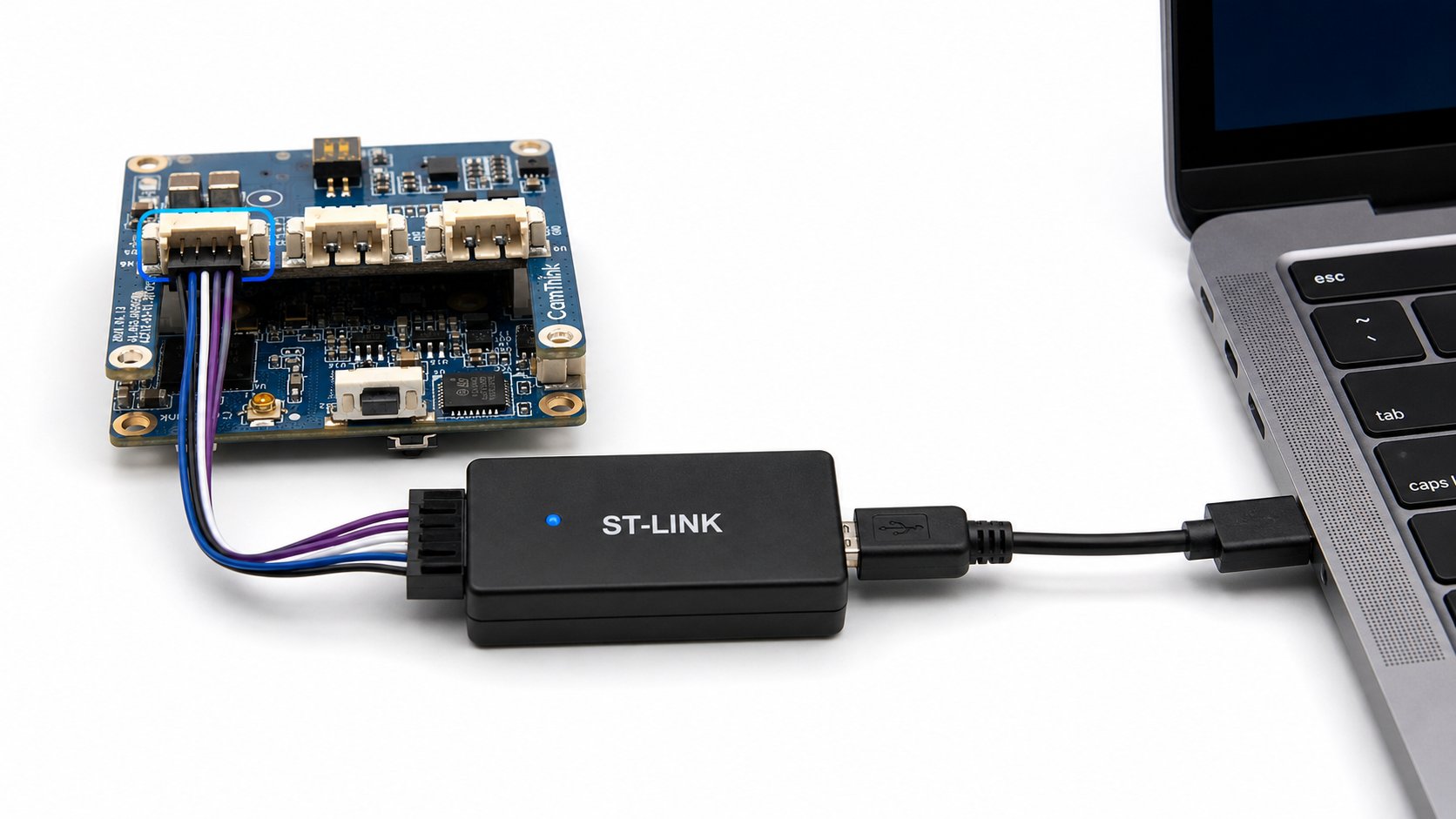
N6-STLINK→ ST-LINK → PC. - Power on or reset the device.
Run the flashing command
From the source directory on the PC, run the required command:
make flash-fsbl
make flash-app
make flash-web
make flash-model
make flash-wifi
To flash all N6 components at once:
make flash
make flash flashes FSBL, App, Web, Model and WiFi, then runs erase-ota. It changes device state; prefer a single-component command for routine development.
Return to run mode
- Power off the device.
- Return
N6-BOOTto OFF. - Power on or reset and wait for the device to start.
4. Flash STM32U0 / WakeCore
STM32U0 runs WakeCore. It has a separate interface and Boot switch and must not use the N6 connection path.
Hardware connection and flashing
- Power off the device.
- Set the interface-board
U0-BOOTswitch toward the printed ON side. - Connect: device
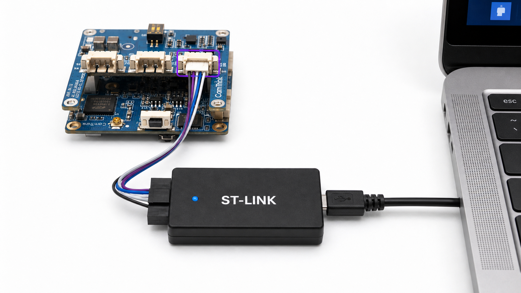
U0-STLINK→ ST-LINK → PC. - Power on or reset the device.
- From the source directory on the PC, run:
make flash-wakecore
Return to run mode
- Power off the device.
- Return
U0-BOOTto OFF. - Power on or reset and check WakeCore wake-up and trigger behavior.
5. Update packages and HEX outputs
The device Web console Firmware Upgrade page uses packaged files. See System Maintenance for the mapping between files and update entries. Upload only a package matching the component and version. Model and App must also use the same STEDGEAI_VARIANT.
To generate combined flashing outputs:
make pack-hex
make pack-hex-wakecore
The main firmware, main firmware plus WiFi and WakeCore HEX outputs target different MCUs and must not be interchanged.
6. Confirm after flashing
- Confirm that the target Boot switch is OFF, then power-cycle the device.
- Open the Web console and check the component version under Firmware Information.
- After updating App, Web or Model, check preview and inference in Feature Debugging.
- After updating WakeCore, check that the device wakes and responds to triggers as expected.
If the PC cannot detect the target, first check device power, the Boot switch position, the selected N6-STLINK or U0-STLINK interface, and whether the other flashing path is still connected.
7. Erase commands
The following commands change device state. Confirm the target device and back up required configuration first:
make erase-nvs
make erase-ota
make erase-all
make erase-chip
erase-chip erases the entire chip and is not a routine build or flashing step.