1. Module Description
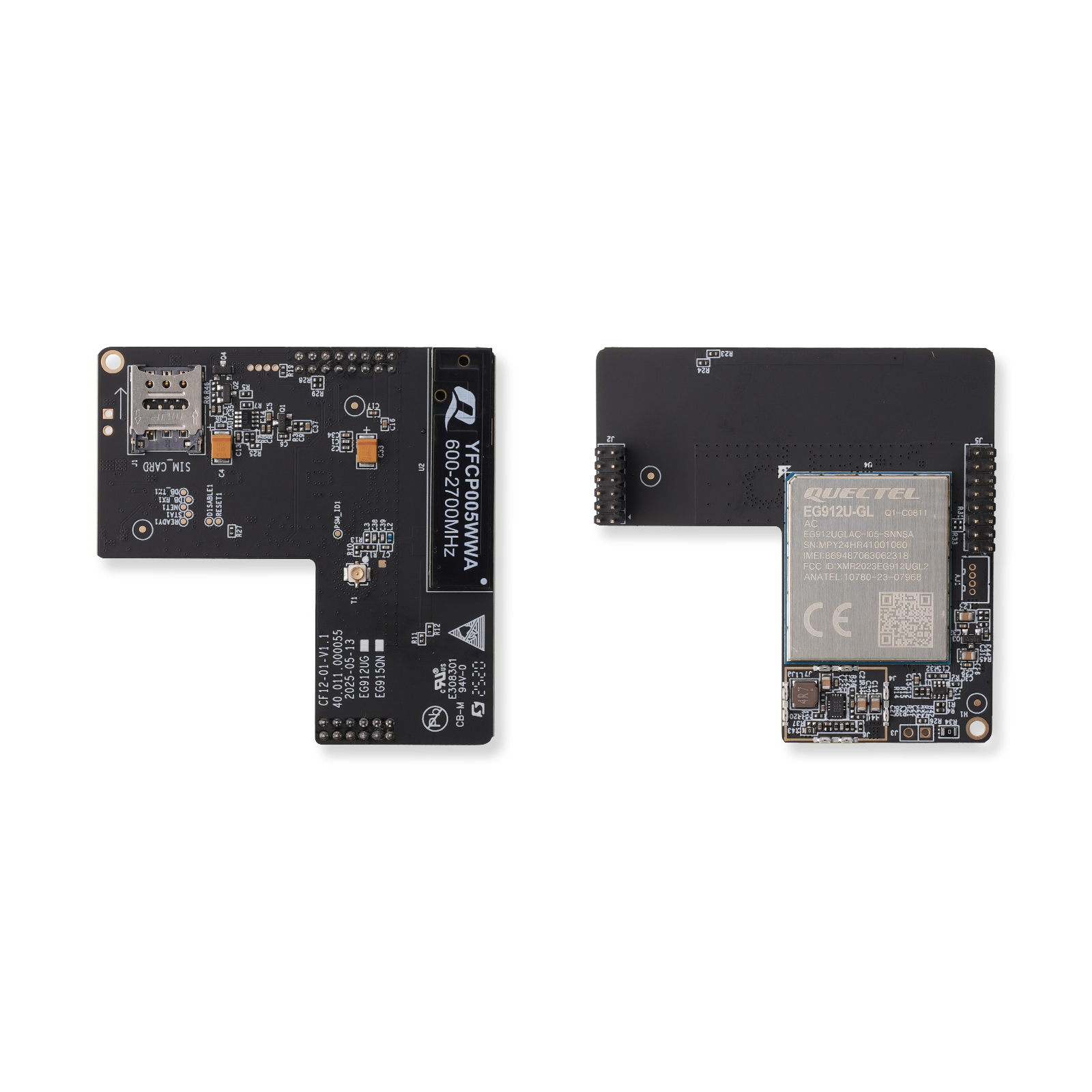
This module is developed based on the EG912U-GL (for regions outside North America) and the EG915Q-NA (for North America).
The EG912U series LTE Cat.1 module is specially designed for M2M and IoT applications, it supports seamless network switching and rich interfaces. Key features include:
EG912U Series Cat.1 Module Specifications
| | EG912U-GL | EG912U-EAL |
|---|
| Network Coverage | Global frequency bands(B1/2/3/4/5/7/8/12/13/17/18/19/20/25/26/28/66 LTE-FDD + B34/38/39/40/41 LTE-TDD) | Europe/Asia-pacific/Latin America(B1/2/3/4/5/7/8/20/28/66 LTE-FDD + B38/40/41 LTE-TDD) |
| Data Transmission Rates | LTE-FDD: 10Mbps(DL)/5Mbps(UL)LTE-TDD: 8.96Mbps(DL)/3.1Mbps(UL) | Same as the global version |
| Optional Functions | GNSS(GPS/GLONASS/BDS/Galileo/QZSS)Bluetooth 4.2 Wi-Fi Scan | Not available |
| Interfaces | 3x UART, USB 2.0, PCM/I2S audio, 2x ADC, SPI/I2C/LCM/Camera/SD card(QuecOpen®) | Same as the global version |
| Antenna | Main antenna + GNSS/Wi-Fi antenna(optional) | Only main antenna |
Cat.1 (EG912U) Module Specifications
| 1 | Module | Quectel EG912UGL |
|---|
| 2 | LTE-FDD | B1/ 2/ 3/ 4/ 5/ 7/ 8/ 12/ 13/ 17/ 18/ 19/ 20/ 25/ 26/ 28/ 66 |
| 3 | LTE-TDD | B34/ 38/ 39/ 40/ 41 |
| 4 | GSM | B2/ 3/ 5/ 8 |
| 5 | Antenna | PCB Antenna |
| 6 | Communication Interfaces | UART |
| 7 | Power Supply | DC 4-6V |
| 8 | Operation Temperature | -20℃ ~ +60℃ |
| 9 | Storage Temperature | -40℃ ~ +85℃ |
| 10 | Dimensions | 60 x 60 mm |
| 11 | Certifications | CE |
EG915 Q Module Specifications
| Module | EG915Q-NA |
|---|
| LTE-FDD | B2/B4/B5/B12/B13/B14/B66/B71B2/B4/B5/B12/B13/B14/B66/B71 |
| Data Transmission Rates | LTE-FDD: 10Mbps(DL)/5Mbps(UL) |
| Interfaces | UART, USB 2.0, PCM, SPI/I2C/LCM/Camera |
| Antenna | Main antenna + GNSS/Wi-Fi antenna(optional) |
Cat-1 (EG915Q) Module Specifications
| 1 | Module | Quectel EG915Q-NA |
|---|
| 2 | LTE-FDD | B2/B4/B5/B12/B13/B14/B66/B71B2/B4/B5/B12/B13/B14/B66/B71 |
| 3 | Antenna | PCB Antenna |
| 4 | Communication Interfaces | UART |
| 5 | Power Supply | DC 4-6V |
| 6 | Operation Temperature | -20℃ ~ +60℃ |
| 7 | Storage Temperature | -40℃ ~ +85℃ |
| 8 | Dimensions | 60 x 60 mm |
| 9 | Certifications | FCC |
Interface Instruction (J1)
The module communicates with the motherboard through the UART interface by J1 interface. The interface is defined as follows:
| PIN# | Pin Name | Functions | Pin Type | Pull Up/Down |
|---|
| 1 | UART_TXD | UART Transmit | OUT | N/A |
| 2 | NC | | | |
| 3 | CAT1_PWR | High=ON;Low=OFF | IN | N/A |
| 4 | NC | | | |
| 5 | NC | | | |
| 6 | NC | | | |
| 7 | UART_RXD | UART Receive | IN | N/A |
| 8 | NC | | | |
| 9 | GND | GND | POWER | |
| 10 | GND | GND | POWER | |
| 11 | NC | | | |
| 12 | NC | | | |
| 13 | VCC_IN | Power Supply | | |
| 14 | 3V3 | 3.3 V power supply | POWER | |
| 15 | VCC_IN | Power Supply | POWER | |
| 16 | 3V3 | 3.3 V power supply | POWER | |
Dimensions
60*60mm