Quick Start
Product Overview
The NE300 series is a high-performance AI smart-camera lineup tailored for IoT deployments. The NE301 reference firmware exposes AI preview/debug, telemetry upload, system configuration, and other core capabilities. This guide helps you learn the feature set from a development-board perspective so you can validate hardware, firmware, and peripherals quickly.
The NE300-MB01 board is a low-power wireless platform that can capture still frames, live streams, and recorded video, while running on-device analytics. It is built around STMicroelectronics' STM32N657L0H3 (Arm® Cortex®-M55) with Wi-Fi 6 and BLE connectivity. OS04C10 and USB cameras can be used for imaging, with an optional Cat-1 modem for backhaul. The design targets low-power edge scenarios that need remote installation flexibility, photo capture, and on-board inference.
Tips: Compared with the turnkey/boxed product documentation, this chapter focuses on developer workflows and feature-level tuning.
Hardware Preparation
What You Need
- NE300-MB01 development board
- Optional daughtercards (see Hardware Components Overview)
Operating Guide
Device Overview
Production samples ship with the standard firmware pre-flashed. Manual flashing isn't required unless the board fails to boot—see the system flashing guide if needed.
Connecting the Board
Key notes
- Power via the USB Type-C port (≥5 V / 1 A)
- All headers feature keyed orientation
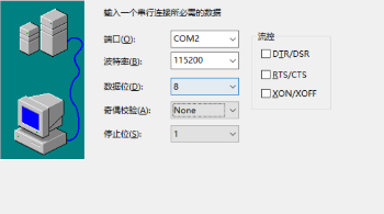
- A 115200 bps debug UART is reserved on the board
Refer to the Hardware Connection Guide for wiring diagrams.
Fast Boot Sequence
- Power up
- Connect a USB power supply (or battery sled if you're running on batteries)
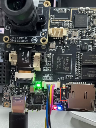
- Check the status LED
- The blue LED in the lower-left corner lights up when the system finishes booting (it may be hidden if the enclosure is installed)
- OS init takes ~1 minute
- Enter configuration mode
- Hold the side button for ~2 seconds to wake the Wi-Fi AP; the CV light board turns blue (visible even with the cover on)
- Connect to the management UI
- Device hotspot SSID:
NE301_XXXXXX - Join the Wi-Fi AP from your phone or laptop
- Browse to http://192.168.10.10
- Device hotspot SSID:
Tips: Joining the device AP will disconnect that phone/laptop from its previous network, so cloud access may pause while you configure the board.
Board-Level Highlights
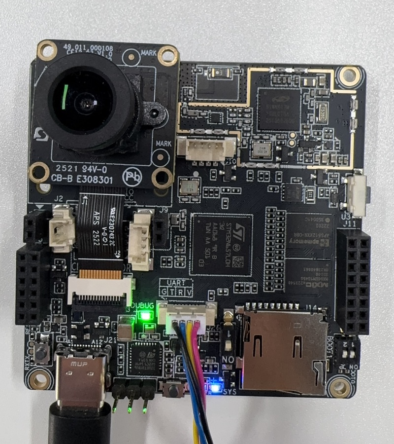
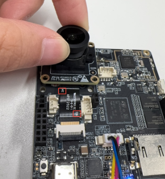
Camera Module Connection
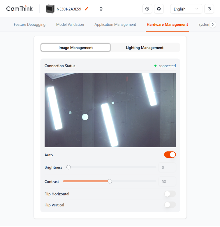
Mind the J1/J2 markings on the ribbon cable. Hold both sides of the lens barrel (avoid fingerprints) and rotate to focus. You can verify focus live under Function Debug or Hardware Management → Image Management on the web UI.
CV Light Board
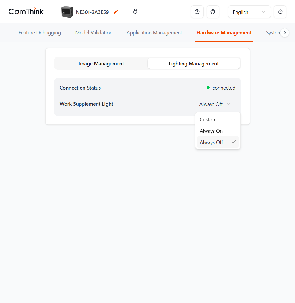
The plug-in light board exposes an AP indicator on the left (solid blue after boot) and a fill light on the right. Configure brightness, toggle, and time windows under Hardware Management → Light Control. Once saved, the fill light fires whenever a capture is triggered.
SD Card Slot
Supports hot swap. Navigate to Storage Management in the web UI to view the card status. If you insert a card after boot, refresh the page or switch tabs to force a status update. Supported file systems are listed in the hardware manual.
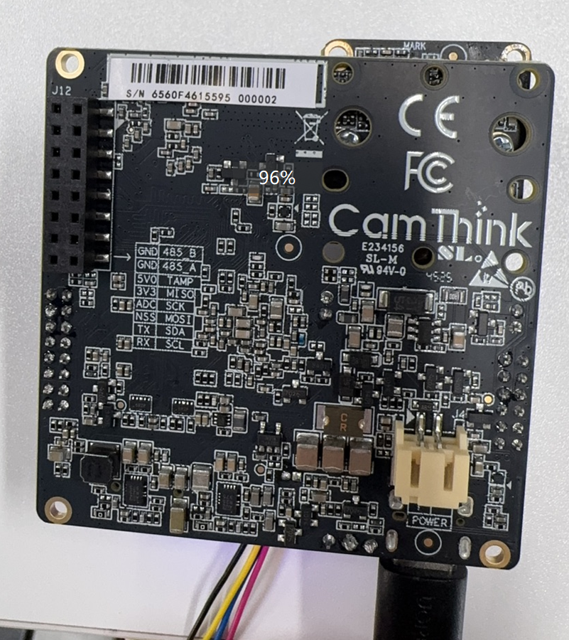
Power Options
Front USB for power/debug, back battery bay, or a plug-in PoE module.
LED States
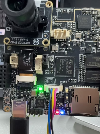
- Red — Power LED, solid when USB power is present
- Blue — AP status LED, mirrors the CV board status once the system is ready
- Green — DEBUG LED, blinks while debugging is active
UART Debugging

The UART harness is keyed to avoid reversed insertion (see the hardware design guide). Use any serial console at 115200 bps to access the debug shell.

Web Configuration
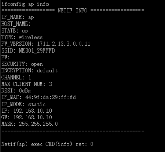
Each device exposes a Wi-Fi AP named NE301_${MAC last 6}. You can also run ifconfig ap info over serial to confirm the SSID.
After joining the AP, browse to 192.168.10.10. The default login is admin / hicamthink. Change the password under System Settings → Device Password Management → Login Password.
Power Modes
Developers typically keep the board on USB power. Once logged into the web UI, switch Function Debug → Power Mode to Full Speed.
Low-power mode targets battery use. After ~90 seconds of inactivity the device sleeps, turning off the blue indicators on both boards and leaving only the red power LED. Hold the side key for 2 seconds to wake it.
Set System Settings → Device Password Management → Sleep Duration to Never if you need the AP up continuously.
Functional Validation Checklist
- Enter sleep mode (confirm the device is in the low-power profile)
- Trigger a capture task (scheduled, button, remote, or IO)
- Review the image quality (resolution, exposure, focus)
- Confirm upstream data delivery (server receives the image)
FAQ
Blurry Preview
Out-of-focus optics are the most common reason for blurry previews. Adjust the focus manually, trying both clockwise and counterclockwise rotations, until the live view is sharp.
Wiring reference:
Unexpected Power Loss
When the board runs off the battery box, flipping DIP switch 1 to NO disconnects the pack and powers the system down. Return it to the original position to resume operation.