System Flashing

The NE503 device software consists of two layers:

LayerNameContentsUpdate Method
System Imagehailo-osLinux kernel, device tree, root filesystemFlashing/upgrade (this document)
Platform Softwarehailo-ne503Platform services, HAL, Web consoleSoftware Deployment

This document covers the initial flashing and subsequent upgrades of the system image. For building and deploying platform software, see Software Deployment.

Workflow Overview​

Choose a path based on the current state of the device:

When to skip Β§2: if the device can reach the U-Boot menu or already boots into Linux, the boot chain is intact β€” go straight to Β§3 or Β§6. You only need Β§2 for a brand-new board or a corrupted bootloader (no U-Boot output on power-up). Interface board MCU firmware (Β§4) is separate from the SoC system image β€” the meta-hailo-os package does not include MCU firmware; it must be flashed separately via ST-LINK/SWD during initial deployment (see Β§4), otherwise peripherals (lens, light, IR, PTZ) will not work.

1. Prerequisites​

1.1 Firmware Package​

Download the firmware package from the open-source repository camthink-ai/meta-hailo-os. After extraction, it contains the following files, grouped by purpose:

Boot-chain components (used by Β§2, 9 files)

FilePurpose
hailo15_uart_recovery_fw.binUART recovery firmware
hailo15_scu_bl.binSCU bootloader
scu_bl_cfg_a.binSCU boot configuration
hailo15_scu_fw.binSCU firmware
u-boot.dtb.signedU-Boot device tree (signed)
u-boot-spl.binU-Boot SPL
u-boot-initial-envU-Boot initial environment variables
customer_certificate.binCustomer certificate
u-boot-tfa.itbU-Boot TF-A image

System image (used by Β§3 / Β§6, 3 files)

FilePurpose
fitImageLinux kernel image
swupdate-image-hailo15-ne503.ext4.gzSystem root filesystem
hailo-update-image-hailo15-ne503.swuSWUpdate upgrade package

Interface board MCU firmware (used by Β§4, 1 file)

Separate from the meta-hailo-os package; provided by CamThink.

FilePurpose
ne503_mcu.elfInterface board MCU (STM32G0B0RET6) firmware

1.2 Host Tools​

Only needed for Β§2 Flash Boot Chain; skip this section if you only do Β§3/Β§5 system-image flashing or upgrades.

Boot-chain flashing in Β§2 supports both Ubuntu and macOS (validated hailo15_board_tools version 1.9.0). hailo15_board_tools is a cross-platform Python wheel; the only differences between the two platforms are how dependencies are installed and the serial device node.

Critical dependency mkenvimage: the hailo15_spi_flash_program tool in Β§2.3 shells out to mkenvimage to build the U-Boot env image. If not installed, the flash crashes while writing the 5th component (U-Boot env), leaving a half-written boot chain. Both platforms must install it first β€” Ubuntu provides it via apt-get install u-boot-tools, macOS via brew install u-boot-tools.

Ubuntu​

# Hailo flashing tool (replace <VERSION> with the actual version; validated version is 1.9.0)
pip install hailo15_board_tools-<VERSION>.whl

# U-Boot utilities (provides mkenvimage, required by Β§2.3)
sudo apt-get update && sudo apt-get install u-boot-tools

Install Hailo flashing tool

Install U-Boot tools

U-Boot tools installed

macOS​

# 1. mkenvimage (required by Β§2.3, otherwise the flash crashes mid-way)
brew install u-boot-tools

# 2. Install the wheel inside a venv (Homebrew Python is PEP 668 externally-managed; a bare pip install is rejected)
python3 -m venv hailo-venv
./hailo-venv/bin/pip install hailo15_board_tools-<VERSION>.whl
# Then use ./hailo-venv/bin/uart_boot_fw_loader and ./hailo-venv/bin/hailo15_spi_flash_program

Serial device node: Ubuntu is typically /dev/ttyACM0; macOS is typically /dev/cu.usbserial-* or /dev/tty.usbserial-*. Pass your actual node to --serial-device-name (see Β§1.4 Hardware Connection for how to find it).

Interface Board MCU Flashing (required by Β§4)​

Also requires an ST-LINK debugger (V2/V3) and STM32CubeProgrammer (validated version 2.19.0; uses the STM32_Programmer_CLI tool). Download and install from st.com; on macOS the CLI is typically at /Applications/STMicroelectronics/STM32Cube/STM32CubeProgrammer/STM32CubeProgrammer.app/Contents/MacOs/bin/STM32_Programmer_CLI.

1.3 TFTP Server​

Required for Β§3 Flash System Image / Β§6 System Upgrade; skip this section if you only do Β§2 boot-chain flashing.

System images are large (100MB+) and must be transferred to the device via TFTP.

Ubuntu​

# Install TFTP server
sudo apt install tftpd-hpa

# Edit configuration
sudo nano /etc/default/tftpd-hpa

Configuration:

TFTP_USERNAME="tftp"
TFTP_DIRECTORY="/var/lib/tftpboot"
TFTP_ADDRESS="0.0.0.0:69"
TFTP_OPTIONS="--secure"

Start the service and deploy firmware files:

sudo mkdir -p /var/lib/tftpboot
sudo chmod -R 777 /var/lib/tftpboot
sudo systemctl restart tftpd-hpa

# Copy firmware files to TFTP directory
cp fitImage swupdate-image-hailo15-ne503.ext4.gz hailo-update-image-hailo15-ne503.swu /var/lib/tftpboot/

macOS​

macOS includes tftpd, which runs on-demand via launchd:

# Create firmware directory
mkdir -p ~/Downloads/Firmware
chmod 777 ~/Downloads/Firmware

# Write launchd configuration
sudo tee /Library/LaunchDaemons/com.tftp.local.plist > /dev/null << 'EOF'
<?xml version="1.0" encoding="UTF-8"?>
<!DOCTYPE plist PUBLIC "-//Apple//DTD PLIST 1.0//EN" "http://www.apple.com/DTDs/PropertyList-1.0.dtd">
<plist version="1.0">
<dict>
<key>Label</key>
<string>com.tftp.local</string>
<key>ProgramArguments</key>
<array>
<string>/usr/libexec/tftpd</string>
<string>-i</string>
<string>/Users/<USER>/Downloads/Firmware</string>
</array>
<key>inetdCompatibility</key>
<dict>
<key>Wait</key>
<true/>
</dict>
<key>InitGroups</key>
<true/>
<key>Sockets</key>
<dict>
<key>Listeners</key>
<dict>
<key>SockServiceName</key>
<string>tftp</string>
<key>SockType</key>
<string>dgram</string>
</dict>
</dict>
</dict>
</plist>
EOF

# Start the service
sudo launchctl load -w /Library/LaunchDaemons/com.tftp.local.plist

# Verify
sudo lsof -i :69

Replace <USER> with your macOS username. Place firmware files in ~/Downloads/Firmware/.

If TFTP reports "Operation not permitted", add /usr/libexec/tftpd to System Settings β†’ Privacy & Security β†’ Full Disk Access, or use /private/tftpboot as the TFTP directory instead.

1.4 Hardware Connection​

  1. Connect the NE503 debug UART to the host using a USB-to-serial adapter

The NE503 debug UART uses 1.8V logic levels. A 1.8V-compatible USB-to-serial adapter is required (common 3.3V adapters may not work reliably). Contact CamThink for the recommended serial adapter board.

  1. Connect the NE503 Ethernet port to the host (direct cable or same switch)

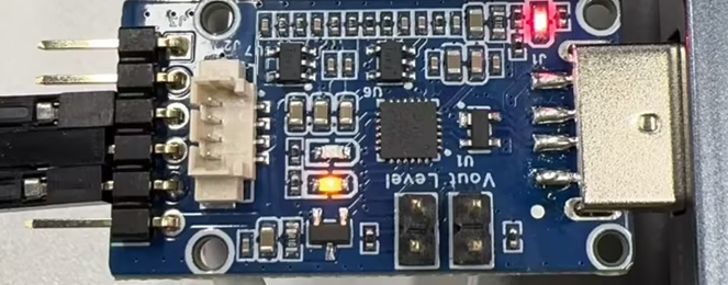
CamThink serial adapter:

CamThink serial adapter

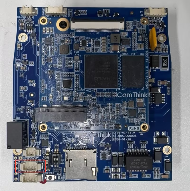
Connected to NE503 board:

NE503 board serial connection

  1. Identify the serial device:
ls /dev/serial/by-id/* -lh
# Example output: usb-1a86_USB_Serial_5B1E071587-if00 -> ../../ttyACM0

Query serial device node

The examples below use /dev/ttyACM0. Replace with your actual device node. On macOS, the device is typically /dev/tty.usbmodem* or /dev/tty.usbserial*.

Open a serial terminal (baud rate 115200). All subsequent flashing logs, U-Boot menu interaction, and system login happen in this terminal:

# Ubuntu (minicom also works)
screen /dev/ttyACM0 115200

# macOS
screen /dev/tty.usbmodem* 115200

On Windows, use SecureCRT or PuTTY at the same 115200 baud rate. To exit screen: press Ctrl+A, then K, then Y.

DIP Switch Modes​

The NE503 uses two DIP switches (BOOT0, BOOT1) to select the power-on behavior. Later sections refer to these modes by name only β€” check this table:

ModeBOOT0BOOT1When to use
UART recovery (flash boot chain)OFFONΒ§2 Flash Boot Chain only
Normal bootOFFOFFΒ§3 Flash System Image onward; daily operation

2. Flash Boot Chain​

Boot chain flashing is only needed for initial deployment or if the bootloader is corrupted. Skip this step during normal operation.

2.1 Enter UART Recovery Mode​

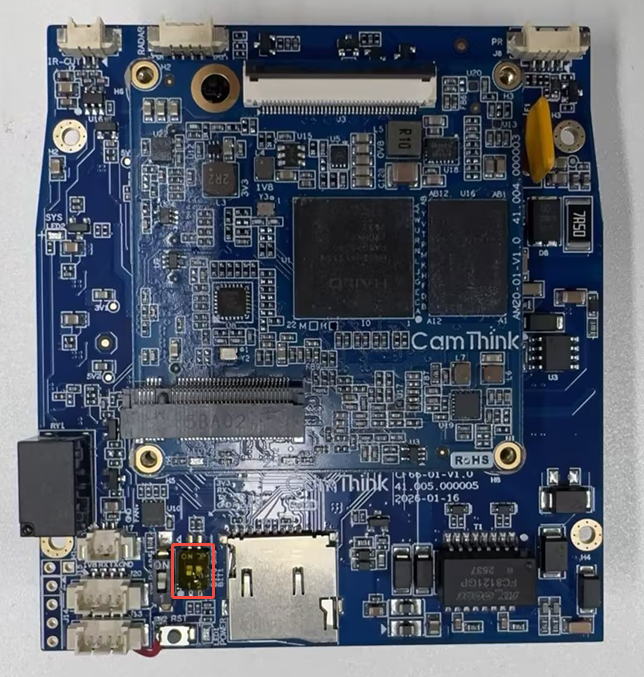
Set the DIP switches to UART recovery mode (BOOT0 OFF, BOOT1 ON; see Β§1.4 DIP Switch Modes):

DIP switch flash mode

Steps:

  1. Switch to UART recovery mode (BOOT0 OFF, BOOT1 ON)
  2. Power on the device via PoE (RJ45 Ethernet port)
  3. Press the Reset button to enter flashing wait state

Reset button

2.2 Load UART Recovery Firmware​

uart_boot_fw_loader \
--serial-device-name /dev/ttyACM0 \
--firmware ./hailo15_uart_recovery_fw.bin

UART recovery firmware loading

2.3 Flash SPI Flash Bootloader Components​

This step writes all bootloader components to SPI Flash, including SCU firmware, U-Boot SPL, device tree, and more:

hailo15_spi_flash_program \
--scu-bootloader ./hailo15_scu_bl.bin \
--scu-bootloader-config ./scu_bl_cfg_a.bin \
--scu-firmware ./hailo15_scu_fw.bin \
--uboot-device-tree ./u-boot.dtb.signed \
--bootloader ./u-boot-spl.bin \
--bootloader-env ./u-boot-initial-env \
--customer-certificate ./customer_certificate.bin \
--uboot-tfa ./u-boot-tfa.itb \
--uart-load \
--serial-device-name /dev/ttyACM0

Expected output:

UART recovery load firmware and script version: 1.4
flash detected, flash jedec_id: 0x9d701700
Programming SCU firmware file: ./hailo15_scu_fw.bin...
Erasing flash from 0x8000 B to 0x39350 B...
Erased successfully
Storage program validation passed successfully
Provided file ./hailo15_scu_fw.bin was successfully programmed
Programming SCU bootloader file: ./hailo15_scu_bl.bin...
Erasing flash from 0x0 B to 0x2c74 B...
Erased successfully
Storage program validation passed successfully
Provided file ./hailo15_scu_bl.bin was successfully programmed
Programming SCU bootloader config file...
Erasing flash from 0x5000 B to 0x502c B...
Erased successfully
Storage program validation passed successfully
Provided file ./scu_bl_cfg_a.bin was successfully programmed
Programming U-Boot SPL file: ./u-boot-spl.bin...
Erasing flash from 0x54000 B to 0x76a2c B...
Erased successfully
Storage program validation passed successfully
Provided file ./u-boot-spl.bin was successfully programmed
Programming U-Boot env file: ./u-boot-initial-env...
Erasing flash from 0x50000 B to 0x54000 B...
Erased successfully
Storage program validation passed successfully
Provided file ./u-boot-initial-env was successfully programmed
Programming Customer certificate file: ./customer_certificate.bin...
Erasing flash from 0x4f000 B to 0x4fa14 B...
Erased successfully
Storage program validation passed successfully
Provided file ./customer_certificate.bin was successfully programmed
Programming u-boot device-tree file: ./u-boot.dtb.signed...
Erasing flash from 0x40000 B to 0x46d84 B...
Erased successfully
Storage program validation passed successfully
Provided file ./u-boot.dtb.signed was successfully programmed
Programming U-Boot & TF-A file: ./u-boot-tfa.itb...
Erasing flash from 0x80000 B to 0x103e80 B...
Erased successfully
Storage program validation passed successfully
Provided file ./u-boot-tfa.itb was successfully programmed

The above is typical output. Actual output may vary in casing or spelling across tool versions (e.g. Storage program validatation), and the SCU bootloader config may be programmed twice (A/B redundant slots). Judge success by each component finally printing successfully programmed and the process exiting with code 0; all 8 components should program successfully.

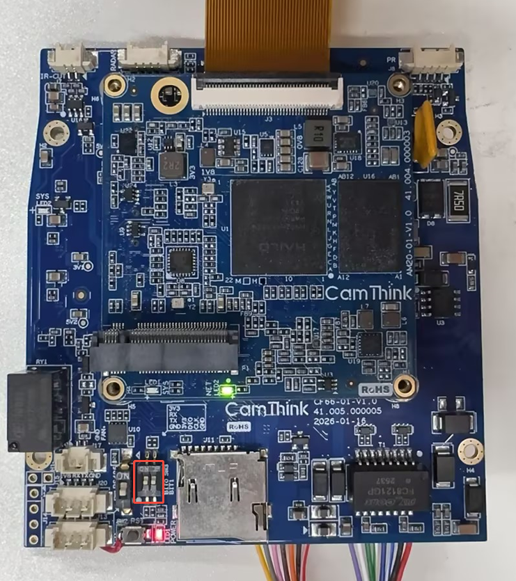
After flashing, restore the DIP switches to normal mode:

  • BOOT0: OFF
  • BOOT1: OFF

DIP switch normal mode

3. Flash System Image​

Once the boot chain is ready, use the U-Boot menu to write the system image to eMMC.

3.1 Enter U-Boot Menu​

Confirm the DIP switches are in normal mode (BOOT0 OFF, BOOT1 OFF; see Β§1.4 DIP Switch Modes β€” if you just finished Β§2, the switches are already in normal mode). Power on the device via PoE through the RJ45 port. The on-board green LED will blink.

PoE power-on

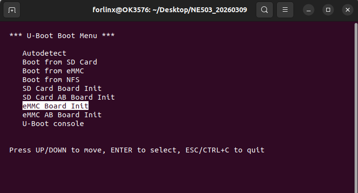
Once powered on, press ↑/↓ keys in the serial terminal to stop autoboot and enter the U-Boot menu:

U-Boot boot menu

Available boot modes:

ModeDescription
AutodetectAuto-detect and boot (for devices with existing system)
Boot from eMMCBoot from eMMC
eMMC Board InitRecommended for first flashing: flash single system to eMMC
eMMC AB Board InitFlash redundant dual-system to eMMC
U-Boot consoleEnter command line mode

3.2 Configure Network​

U-Boot pulls images from the host pointed to by serverip β€” i.e. the host running your TFTP server from Β§1.3: the device IP defaults to 10.0.0.1 and serverip to 10.0.0.2. Before flashing, put the TFTP host and the device on the same subnet. Choose one of the following depending on the host's subnet.

Option 1 (recommended): put the host on the 10.0.0.x subnet. For a direct connection, assign the host NIC a static IP of 10.0.0.2 and leave the device at its default 10.0.0.1 β€” no U-Boot console needed:

# Ubuntu (replace the interface name, e.g. eth0 / enp0s25)
sudo ip addr add 10.0.0.2/24 dev eth0
# macOS: System Settings β†’ Network β†’ Ethernet β†’ IPv4 Manual
# IP address 10.0.0.2 Subnet mask 255.255.255.0

Option 2: keep the host on another subnet and change the device IP to match. In the U-Boot menu, select U-Boot console and use setenv to modify the device environment. The defaults are shown below (use to confirm or reset back to the default network):

setenv ipaddr 10.0.0.1            # Device IP (default)
setenv serverip 10.0.0.2 # TFTP server (host) IP (default)
saveenv
reset

If the host is on another subnet (e.g. 192.168.93.x), replace the ipaddr / serverip above with addresses on the host's subnet: ensure the device ipaddr is on the same subnet as the host, and serverip is the host IP.

3.3 Execute Flashing​

Return to the U-Boot menu and select eMMC Board Init. The device will automatically:

  1. Download fitImage (kernel) via TFTP into memory
  2. Download swupdate-image-hailo15-ne503.ext4.gz (root filesystem) via TFTP into memory
  3. Verify image signatures (RSA-3072 + SHA-256)
  4. Apply the .swu upgrade package via SWUpdate to write the system to eMMC

eMMC Board Init flashing (1/2)

eMMC Board Init flashing complete (2/2)

Relationship between the three system-image files: fitImage (kernel) and swupdate-image-hailo15-ne503.ext4.gz (root filesystem) are packed into hailo-update-image-hailo15-ne503.swu (the SWUpdate bundle); after eMMC Board Init fetches it over TFTP, SWUpdate verifies the signature and writes the system to eMMC. All three must be placed in the TFTP directory from Β§1.3.

The device reboots into Linux after flashing completes.

4. Interface Board MCU Firmware​

The interface board has a dedicated MCU (STM32G0B0RET6, Cortex-M0+) that manages all peripherals β€” lens, light, IR-CUT, PTZ, RS-485, alarm β€” and communicates with the core board over UART0. This MCU firmware is separate from the hailo-os system image: the meta-hailo-os package does not include MCU firmware and it must be flashed independently.

If you skip this: all peripherals fail β€” camera-daemon's lens bridge keeps reporting lens_state_get failed: -2810, device-control's MCU query times out, and GET /api/v1/device/status returns 500 (the Web console shows "internal server error").

When required: mandatory for initial deployment; the same flow applies to MCU firmware upgrades. This step is independent of the SoC flashing in Β§2 Flash Boot Chain / Β§3 Flash System Image β€” order does not matter, but both must be done before Β§7 Verification.

4.1 Prerequisites​

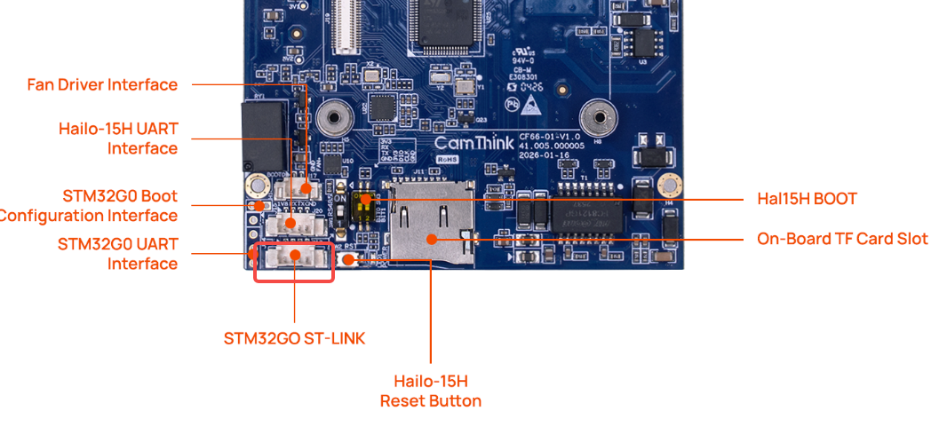
  • Hardware: an ST-LINK debugger (V2/V3) connected to the interface board's SWD port (PA13/SWDIO, PA14/SWDCLKΒ·BOOT0, NRST, GND, 3V3 VREF). Pinout in AIPC Board Connection.

ST-LINK (SWD debug port) location on the interface board

  • Power: the device must be powered (PoE) β€” ST-LINK does not power the board; the MCU is powered by the device supply. After SWD hookup, VREF should read ~3.2V.
  • Host tool: STM32CubeProgrammer (see Β§1.2); uses the STM32_Programmer_CLI tool.
  • Firmware: ne503_mcu.elf (see Β§1.1 Firmware Package).

BOOT0 does not need to be set β€” SWD works in normal boot mode (PA14 is the shared SWDCLK/BOOT0 pin). The SoC can only reset the MCU via H_GPIO_18, not control BOOT0, so MCU firmware must be flashed via ST-LINK/SWD and cannot be done from the SoC alone.

4.2 Verify the SWD Connection​

STM32_Programmer_CLI -c port=swd

Expected output (confirming the STM32G0B0 is reached):

Device name : STM32G0B0xx/B1xx/C1xx
Flash size : 512 KBytes
Device CPU : Cortex-M0+
Voltage : 3.22V

If it reports No STM32 device found: check the SWD wiring (SWDIO/SWDCLK/NRST/GND), confirm the device is powered, and confirm the host sees the ST-LINK (STM32_Programmer_CLI -l should list the probe).

4.3 Flash​

STM32_Programmer_CLI -c port=swd -e all -w ./ne503_mcu.elf -v -rst

This performs: connect SWD β†’ mass erase β†’ write ne503_mcu.elf β†’ verify β†’ reset & run. Success is Mass erase successfully achieved, File download complete, Application is running, exit code 0.

4.4 Verify​

If platform software is already deployed on the SoC, after the device boots:

curl -s -H "Authorization: Bearer <token>" http://<device-ip>:8080/api/v1/device/status
# returns 200; data.mcu_version / mcu_temp_c / light_sensor etc. have values
  • camera-daemon no longer reports lens_state_get failed: -2810.
  • The Web console Device Status panel shows MCU temperature, light sensor, IR-CUT, PTZ data.

The MCU firmware version is independent of the platform software version (e.g. platform v1.2.0 ↔ MCU firmware 0.1.0.0); each is upgraded separately. Disconnecting the ST-LINK after flashing does not affect operation.

5. System Login​

After flashing, the device reboots automatically. Log in via serial console or SSH:

  • Username: root
  • Password: root

System login

For system checks after logging in, see Β§7 Verification.

6. System Upgrade​

This section covers system image upgrades, performed in-place via the SWUpdate mechanism using .swu packages.

6.1 U-Boot TFTP Upgrade​

A full system-image upgrade reuses the same flow from Β§3.3 (U-Boot menu β†’ eMMC Board Init β†’ TFTP β†’ SWUpdate writes eMMC); the only difference is replacing the .swu package in the TFTP directory with the new version. No need to redo Β§2 boot chain.

Brief steps:

  1. Overwrite the old hailo-update-image-hailo15-ne503.swu with the new version in the TFTP directory from Β§1.3
  2. Power on in normal mode, enter the U-Boot menu (press ↑/↓ to stop autoboot), and select eMMC Board Init
  3. The device automatically downloads the new .swu package over TFTP; SWUpdate writes it to eMMC
# Upgrade log example
hailo-update-image-h 9% |*** | 72.1M 0:03:49 ETA

The .swu package is large (~100MB+). Over 100Mbps Ethernet the full upgrade takes about 5-10 minutes. Do not power off or disconnect during the upgrade.

6.2 Runtime Firmware Update​

Steps for online system-image upgrades via the SWUpdate CLI from within a running Linux system are pending and will be provided by the engineering team. For runtime deployment of platform software (ai-runtime, Web console, etc.), see Software Deployment.

7. Verification​

After flashing or upgrading, verify the following:

# 1. Kernel version
uname -r
# 5.15.x (yocto-standard)

# 2. Filesystem
df -h /
# /dev/mmcblk1p2 3.6G 3.xG xxM xx% /

# 3. Hailo kernel modules (NPU / ISP / video pipeline)
lsmod | grep hailo
# hailo_integrated_nnc / hailo15_isp / hailo15_video_cap ...

# 4. Network interface
ip addr show eth0

# 5. Platform services (if platform software is deployed)
systemctl status ai-runtime camera-daemon app-manager event-bus device-control platform-api

Device nodes: the system image lives on eMMC (/dev/mmcblk1) and the boot chain on SPI Flash (/dev/mtdblock0). The Hailo NPU is provided by the hailo_integrated_nnc kernel driver and is not necessarily exposed as a /dev/hailo* device node β€” use lsmod | grep hailo to verify the driver is loaded.

8. Troubleshooting​

Common issues are listed in operational order (Β§2 boot chain β†’ Β§3 system image β†’ Β§6 upgrade). Each follows the pattern: Symptom β†’ Cause β†’ Resolution.

8.1 Boot-Chain Flashing Issues​

Symptom: uart_boot_fw_loader or hailo15_spi_flash_program is unresponsive / reports a serial error

  • Cause: The DIP switches are not in UART recovery mode, the serial device node is wrong, or the serial adapter is not 1.8V-level.
  • Resolution:
    • Confirm the DIP switches are BOOT0 OFF, BOOT1 ON (UART recovery mode, see Β§1.4 DIP Switch Modes), and that Reset has been pressed;
    • Confirm --serial-device-name points to the correct node (on Ubuntu, typically /dev/ttyACM0);
    • Confirm the serial adapter is 1.8V-compatible (see Β§1.4 Hardware Connection).

Symptom: hailo15_spi_flash_program reports could not connect to the recovery agent; or crashes mid-way (e.g. mkenvimage not found, or write didn't succeeded), leaving the boot chain half-written

  • Cause: The device is not in UART recovery mode; or the host is missing mkenvimage (see Β§1.2); or a previous tool crash left the device's UART recovery agent in a degraded state, so on retry the flash writes receive no ACK β€” even erasing-without-writing, which makes the boot chain less complete.
  • Resolution:
    1. Confirm the DIP switches are in UART recovery mode (BOOT0 OFF, BOOT1 ON), and that mkenvimage is installed on the host (Ubuntu: u-boot-tools; macOS: brew install u-boot-tools);
    2. Fully power-cycle the device (unplug PoE β†’ wait 3 seconds β†’ re-apply), keep the DIP switches unchanged, then press Reset once more β€” a single Reset is usually insufficient to reset a degraded recovery agent;
    3. Run uart_boot_fw_loader + hailo15_spi_flash_program back-to-back in a single recovery session, without leaving a long gap between them.
  • A corrupted boot chain is always recoverable: UART recovery runs from the SoC's masked ROM and is independent of SPI Flash contents.

8.2 TFTP & Network Issues​

Symptom: U-Boot reports TFTP error: 'Access violation' (2) or download times out

  • Cause: The TFTP server is not running, or firmware files are missing from the TFTP directory / have insufficient permissions.

  • Resolution:

    # Ubuntu: check service status and directory
    sudo systemctl status tftpd-hpa
    ls -la /var/lib/tftpboot/
    # macOS: check port 69 listener
    sudo lsof -i :69

    Ensure fitImage, swupdate-image-hailo15-ne503.ext4.gz, and hailo-update-image-hailo15-ne503.swu are present in the TFTP directory and readable.

Symptom: macOS TFTP reports Operation not permitted

  • Cause: macOS privacy protection prevents tftpd from reading user directories.
  • Resolution (either):
    • System Settings β†’ Privacy & Security β†’ Full Disk Access β†’ Add /usr/libexec/tftpd
    • Change the TFTP directory to /private/tftpboot

Symptom: U-Boot menu is reachable, but TFTP download is unresponsive

  • Cause: The host and device are on different subnets, or the host IP is not the address pointed to by the device's serverip.
  • Resolution: Check Β§3.2 Configure Network β€” set the host to 10.0.0.2 and leave the device at its default 10.0.0.1; or test connectivity manually from the U-Boot console with tftp 0x80800000 fitImage.

8.3 eMMC Flashing Issues​

Symptom: Selecting eMMC Board Init fails or hangs

  • Cause: No network connectivity, missing TFTP files, or image signature verification failure (corrupted files).
  • Resolution:
    • Check the Ethernet cable and IP configuration (Β§3.2);
    • Confirm the files in the TFTP directory are complete and not truncated;
    • Re-download the firmware package from the open-source repository to overwrite any corrupted files.

8.4 Upgrade Interruption Recovery​

Symptom: Power loss during upgrade leaves the device unbootable

  • Cause: The interruption left the eMMC system image or boot chain incomplete.
  • Resolution:
    1. If the boot chain is corrupted (no U-Boot menu), re-execute Β§2 Flash Boot Chain;
    2. Re-execute Β§3 Flash System Image to write a complete image.

8.5 U-Boot Fails to Boot​

Symptom: No U-Boot menu output on the serial terminal after power-on

  • Cause: The DIP switches are not in normal mode, or the boot chain is not flashed / is corrupted.
  • Resolution:
    • Confirm the DIP switches are in normal mode (BOOT0 OFF, BOOT1 OFF);
    • If there is still no output, re-execute Β§2 Flash Boot Chain.

8.6 Interface Board MCU Issues​

Symptom: the Web console shows "internal server error"; GET /api/v1/device/status returns 500 and takes ~5s; camera-daemon logs lens_state_get failed: -2810 repeatedly

  • Cause: the interface board MCU firmware is not flashed (or is corrupted), so the MCU does not respond on UART0 and device-control's query times out.
  • Resolution: flash ne503_mcu.elf via ST-LINK/SWD per Β§4. After flashing, device/status should return 200 with mcu_version and other fields.

Symptom: STM32_Programmer_CLI -c port=swd reports No STM32 device found

  • Cause: wrong SWD wiring, device not powered, or the host does not see the ST-LINK.
  • Resolution: verify the SWD wiring (SWDIO/SWDCLK/NRST/GND/VREF); confirm the device is powered via PoE (VREFβ‰ˆ3.2V); STM32_Programmer_CLI -l should list the ST-LINK probe.