Sensor Extension Board
This guide describes how to use the NE301 sensor extension board to quickly set up sensor demos for various application scenarios.
1. Overview
The NE301 platform provides standardized sensor expansion capabilities. The sensor extension board connects via a unified I2C bus, managed by an open-source driver layer. It supports plug-and-play operation and custom sensor integration, providing a flexible hardware foundation for application-specific requirements.
Open Architecture
NE301 sensor expansion is built on standard hardware interfaces and open-source drivers, allowing developers to freely adapt and extend:
- Standard I2C interface: I2C bus 1 with 7-bit addressing (0x03–0x77), compatible with mainstream I2C sensors
- Standard SPI display: SPI6 interface driving ST7789VW TFT display (240×240 RGB565) for real-time sensor data visualization
- Open-source driver layer: Complete C driver code available on GitHub at
Custom/Hal/SensorExt/, including I2C bus abstraction, sensor drivers, CLI debug commands, and TFT display output - Unified CLI command: The
sexpcommand starts all sensor data acquisition and display with a single line
Expansion Capabilities
| Method | Description |
|---|---|
| Plug and play | Sensor extension board pre-integrates 9 sensors, ready to use upon connection |
| Custom sensors | Connect any compatible sensor via I2C bus, write adapters referencing open-source drivers |
| Display output | Built-in TFT/OLED driver supports real-time sensor data text overlay and thermal imaging pseudo-color rendering |
| API integration | Open-source C APIs (sht3x_init(), vl53l1x_get_result(), etc.) can be integrated into user applications |
Supported Sensors
| Sensor | Model | Specifications | Typical Applications |
|---|---|---|---|
| Temperature/Humidity | SHT3x | Temperature ±0.3°C, Humidity ±2%RH | Environmental monitoring, warehouse management, overheating protection |
| Ambient Light | LTR-31x | Visible + IR 16-bit detection | Lighting control, day/night switching, intrusion detection |
| 6-axis IMU | LSM6DSR | Accelerometer + Gyroscope + Temperature | Orientation detection, vibration monitoring, fall detection |
| Short-range ToF | VL53L1X | Laser ranging 1.3m (short) / 4m (long) | Proximity detection, gesture recognition, collision warning |
| Long-range Laser | DTS6012M | d-ToF, 18m range (12m@160Klux), 905nm, FOV<2° | Remote target detection, distance monitoring, perimeter security |
| IR Thermal Imaging | MLX90642 | 32×24 pixel temperature matrix, ±1°C, FOV 110°×75° / 45°×35° | Non-contact temperature measurement, thermal distribution detection, human presence detection |
| PIR Human Detection | NP624M-F | Digital dual-element, RF interference resistant, 5μA, VIN:1.6~3.6V | Human motion detection, intrusion alarm, automatic lighting |
| mmWave Radar | RKB1161LX1 | 24GHz, UART, 68μA power consumption, 20×20×1.0mm | Human detection, presence sensing, micro-motion detection |
| MEMS Microphone | LMA3729T381-OY3S | MEMS MTC, sensitivity -38dB, SNR=63dB | Voice capture, sound detection, ambient audio monitoring |
Supported Displays
| Type | Size | Interface | Resolution | Color | Dimensions (mm) |
|---|---|---|---|---|---|
| OLED | 0.96" | I2C, 4PIN | 128×64 | Blue | 24.7(L)×27(W)×11.3(T) |
| TFT | 1.14" | SPI, IPS | 135×240 | 65K colors | 31.4×28×11.3 |
| TFT | 1.54" | SPI, IPS | 240×240 | 262K colors | 32(W)×43.7(H)×5.32(T) |
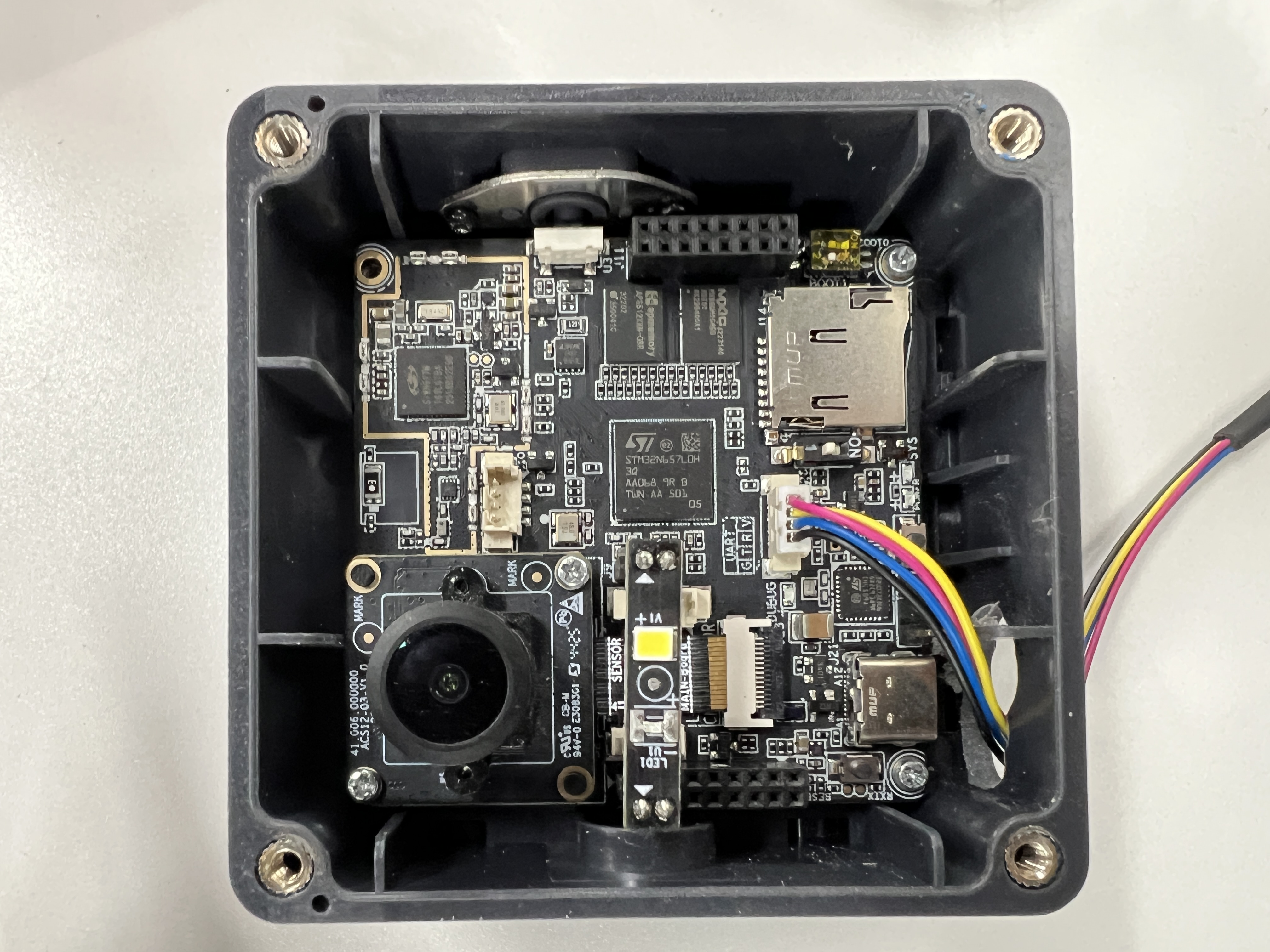
2. Hardware Preparation and Assembly
Required Hardware
| Component | Description |
|---|---|
| NE301 development board | Pre-installed system firmware |
| Sensor extension board | Pre-integrated 9 sensors |
| Display | 0.96" OLED / 1.14" TFT / 1.54" TFT (bundled with extension board, optional) |
| Speaker | HDK-302008ZA-3C13, 30×20mm, 1.5W, 8Ω, 90dB (optional) |
| USB-C cable | For serial debugging and power supply |
| Debug tool | Serial terminal (e.g., minicom, PuTTY) |
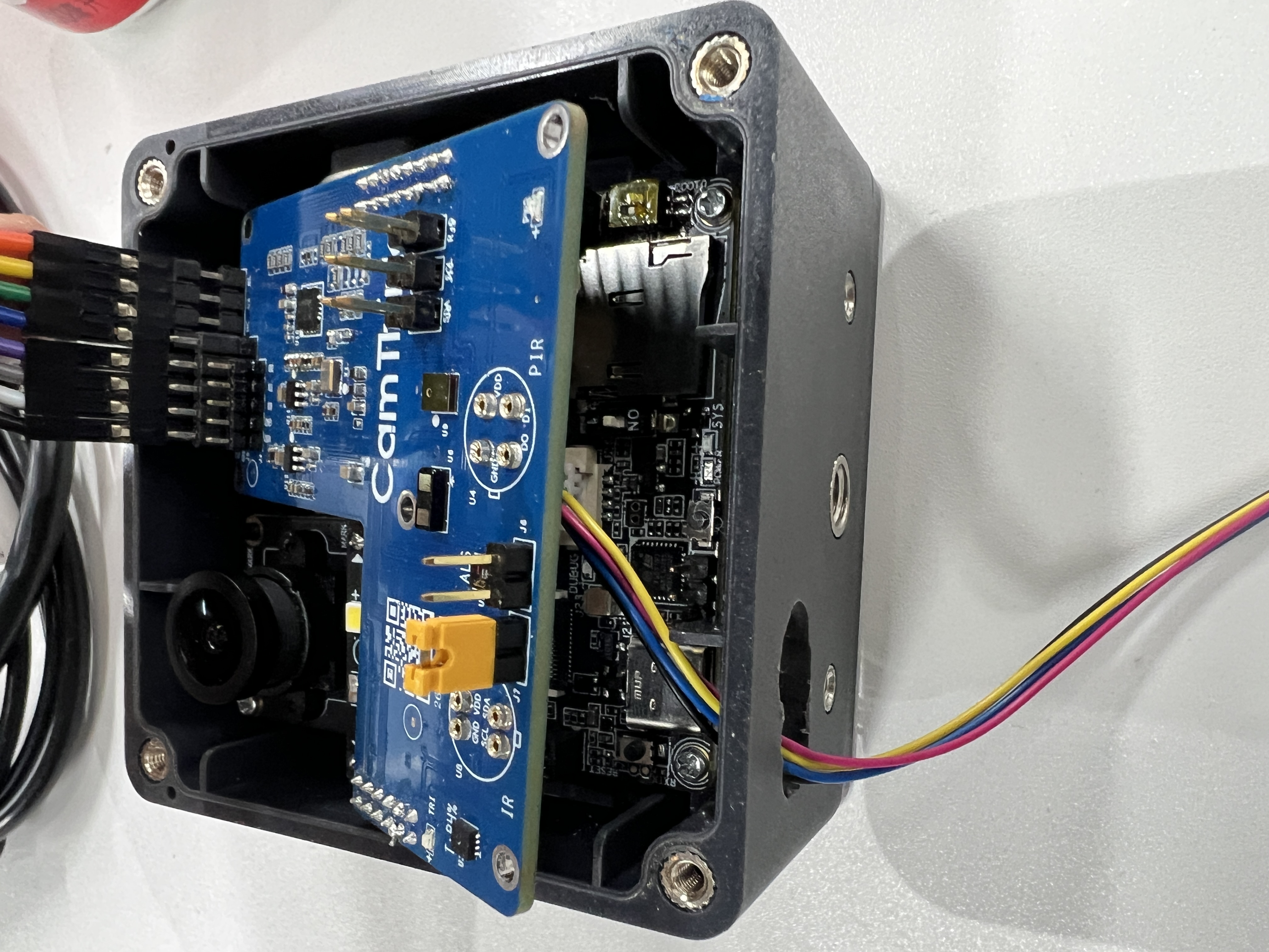
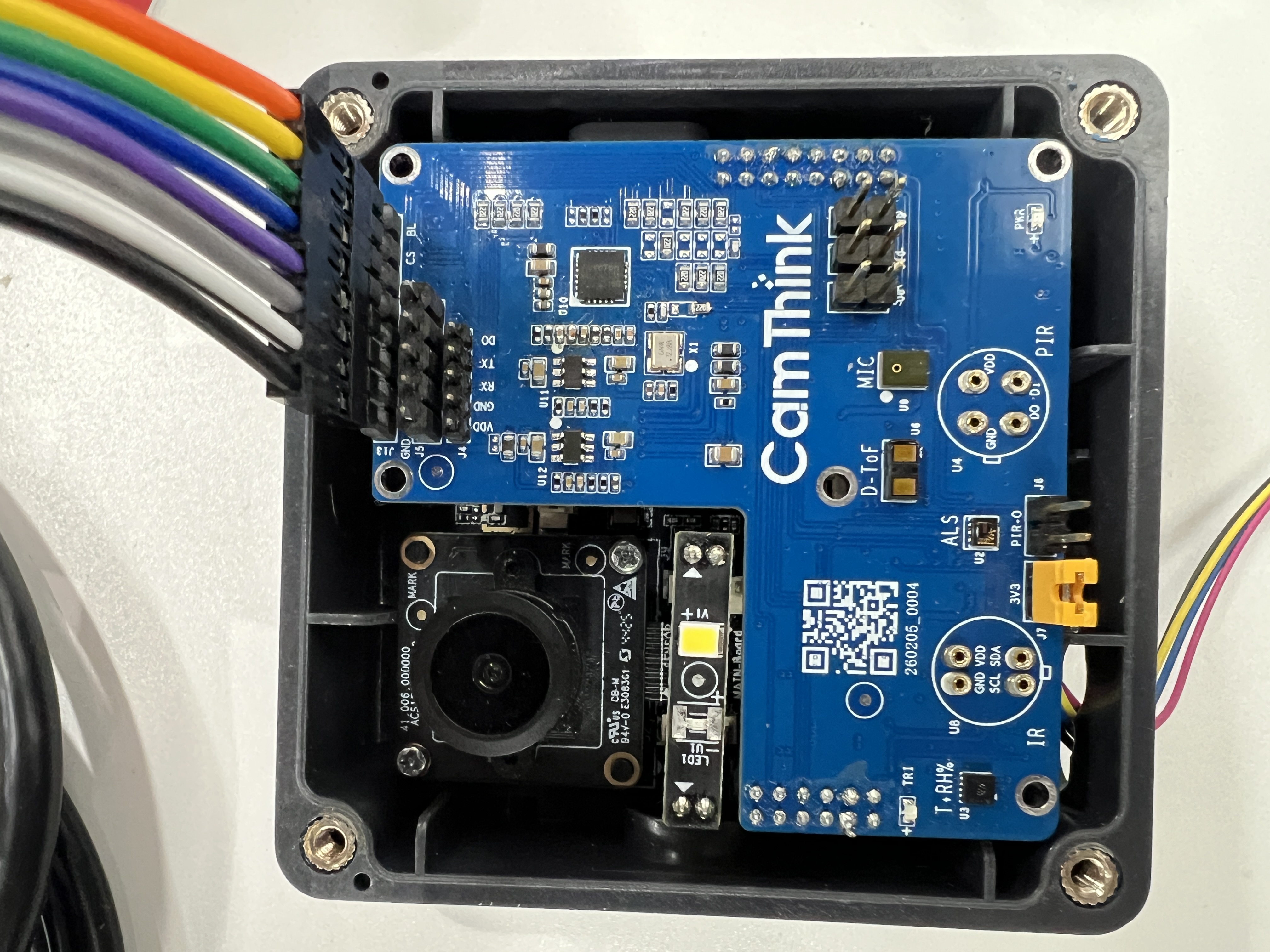
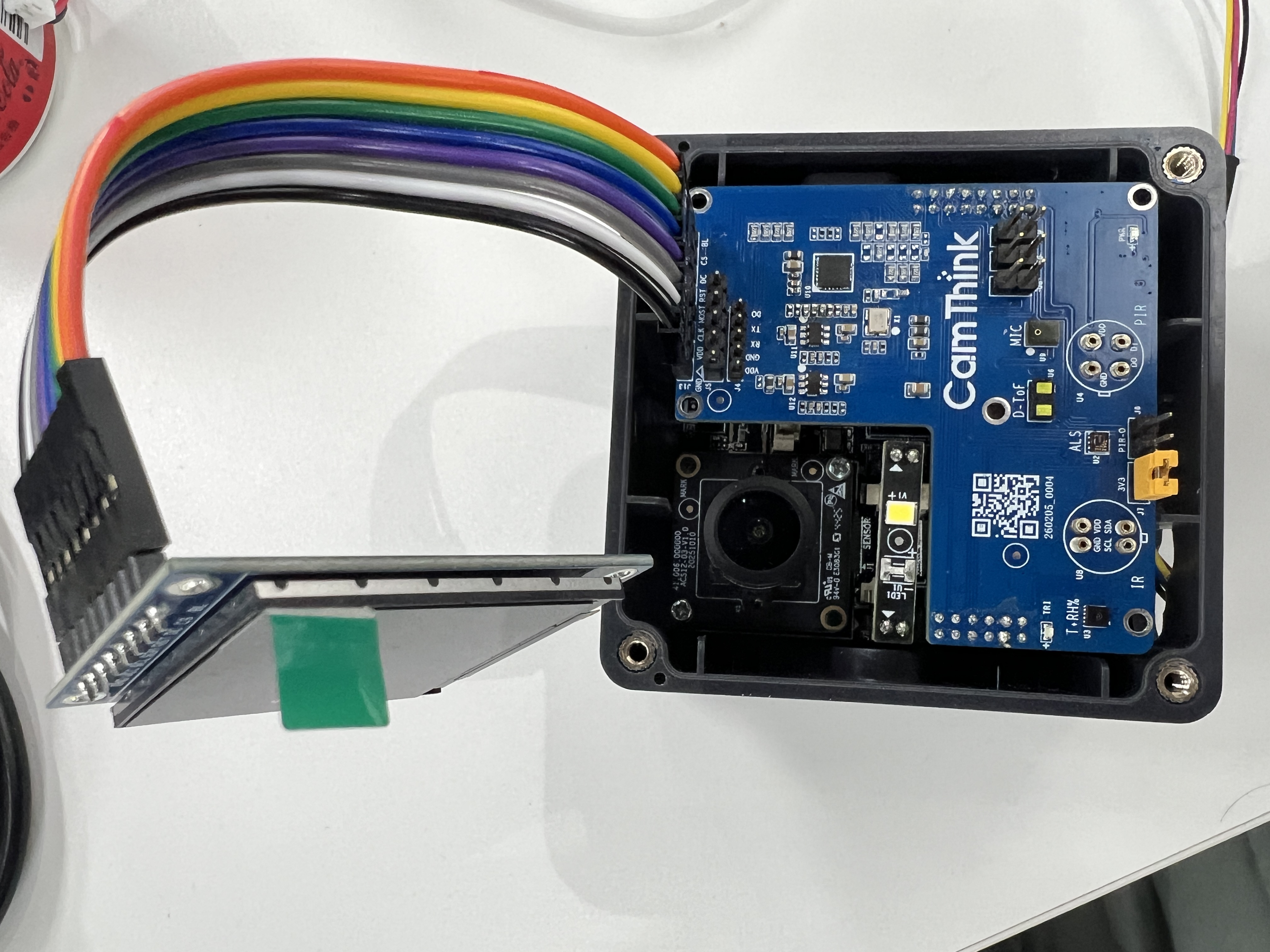
Assembly Steps
Step 1: Align the sensor extension board with the NE301 expansion connector and press to seat
Step 2: Connect the TFT display to the SPI6 interface on the extension board
Step 3: Connect NE301 via USB-C and open the serial terminal
Note: The TFT display and NAU881x audio codec share the SPI6 interface. They are mutually exclusive via resistor soldering configuration. To use audio functionality, switch to an audio-configured extension board.
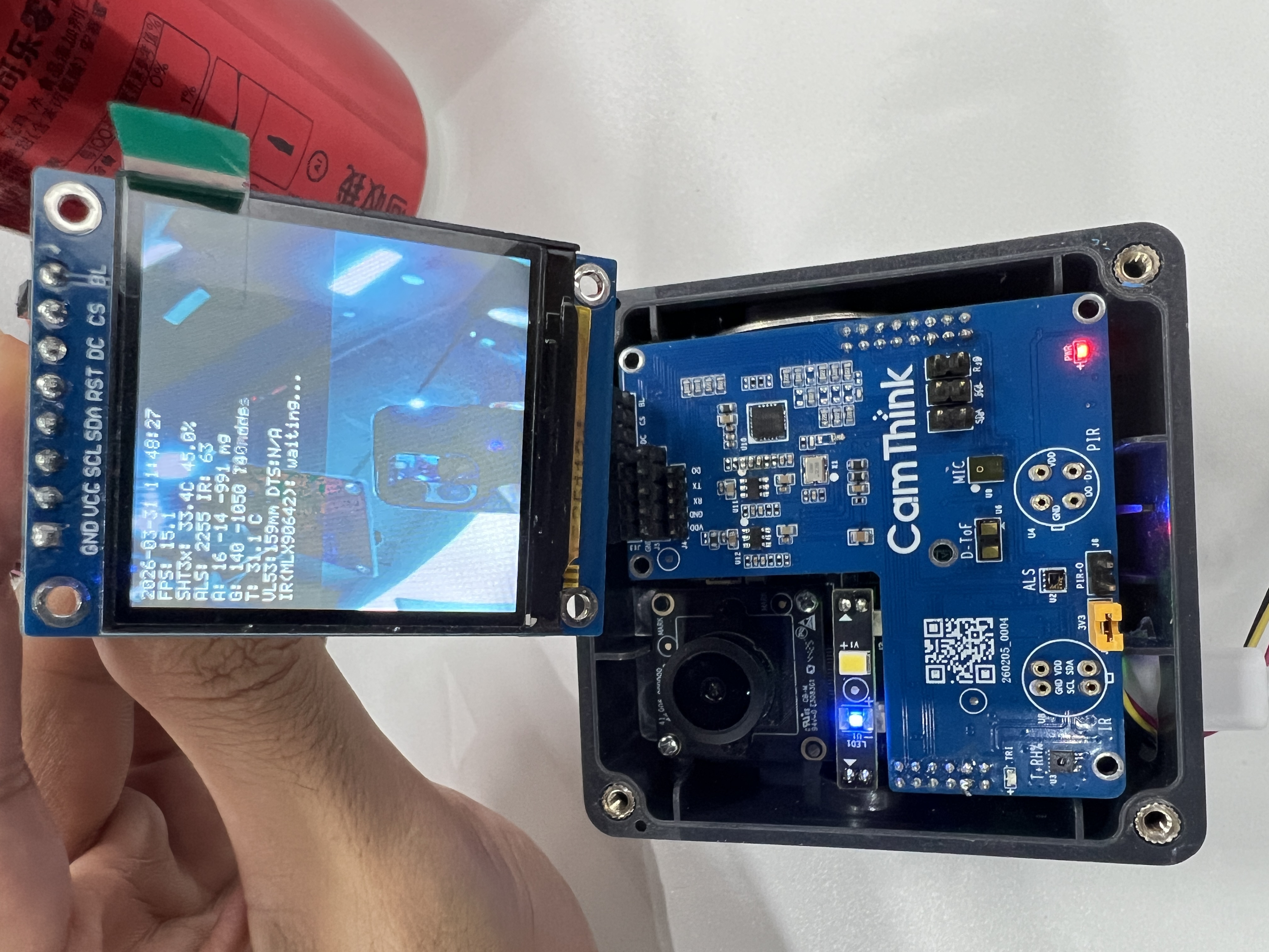
After assembly, the NE301 should appear as follows:
3. Quick Start
3.1 Scan I2C Bus
After connecting the serial terminal, run the I2C scan command to verify all sensors are online:
AICAM> i2c_tool detect
Scanning I2C bus 1, address range 0x03-0x77
      00 01 02 03 04 05 06 07 08 09 0a 0b 0c 0d 0e 0f
00:          -- -- -- -- -- -- -- -- -- -- -- -- --
10: -- -- -- -- -- -- -- -- -- -- 1a -- -- -- -- --
20: -- -- 22 -- -- -- -- -- -- 29 -- -- -- -- -- --
30: -- -- -- -- -- -- -- -- -- -- -- -- -- -- -- --
40: -- -- -- -- 44 -- -- -- -- -- -- -- -- -- -- --
50: -- -- -- -- -- -- -- -- -- -- -- -- -- -- -- --
60: -- -- -- -- -- -- 66 -- -- -- 6a -- -- -- -- --
70: -- -- -- -- -- -- -- --
Complete sensor list:
| Address | Sensor | Address | Sensor |
|---|---|---|---|
| 0x1a | NAU881x audio codec | 0x44 | SHT3x temperature/humidity |
| 0x22 | LTR-31x ambient light | 0x51 | DTS6012M laser ranging |
| 0x29 | VL53L1X ToF ranging | 0x66 | MLX90642 IR thermal imaging |
| 0x6a | LSM6DSR 6-axis IMU |
All sensors share I2C bus 1. A missing sensor does not affect the operation of other sensors.
3.2 Start Sensor Data Acquisition
Run the following command to start sensor data acquisition and TFT display:
AICAM> sexp start
This command will:
- Initialize all sensors (I2C bus 1)
- Start a 200ms periodic sensor reading thread
- Display sensor data in real time on the TFT screen
- The
irparameter enables infrared thermal imaging mode (no camera required)
Once started, the TFT display will show all sensor data in real time:
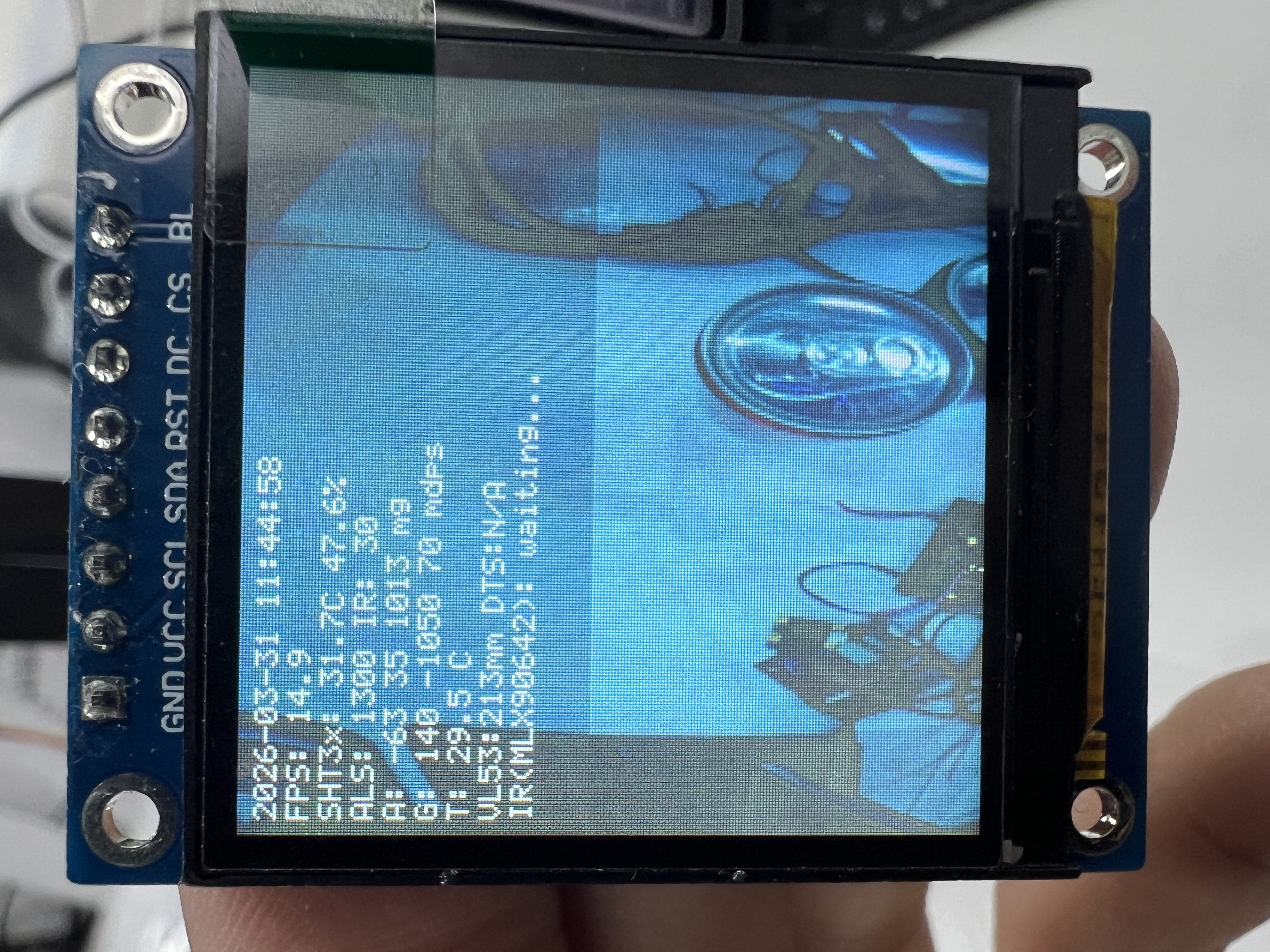
3.3 View Sensor Data
The upper text area of the TFT screen displays real-time readings from each sensor:
SHT3x: 33.4 C 45.0%       ← Temperature/Humidity
ALS: 2255 IR: 63           ← Ambient light (visible + IR)
VL53:159 mm                ← Short-range ToF ranging
DTS:N/A mm                ← Long-range laser ranging
A: 16 -14 -991 mg           ← Accelerometer (3-axis)
G: 140 -1050 140 mdps      ← Gyroscope (3-axis)
3.4 IR Thermal Imaging
Run the following command to start IR thermal imaging mode:
AICAM> sexp start ir
This command will:
- Initialize all sensors (I2C bus 1)
- Start the MLX90642 IR thermal imaging array (32×24 pixels)
- Display thermal imaging on the lower half of the TFT screen (pseudo-color rendering, blue→green→yellow→red spectrum)
- Display all sensor text data on the upper half simultaneously
The top of the TFT screen shows thermal imaging statistics:
MLX: min 16.4 C max 28.8 C avg 21.6 C
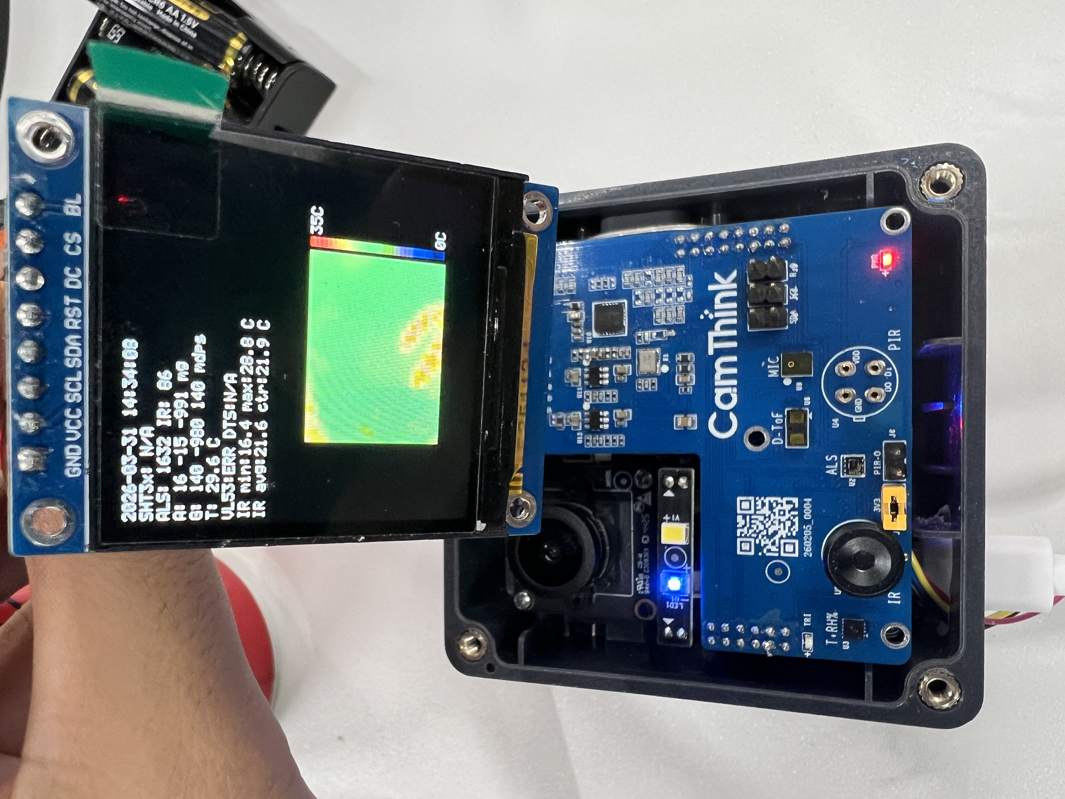
Move your hand near the sensor area to observe real-time temperature changes in the thermal imaging display.
Tip: You can also use sexp start (without the ir parameter) to overlay sensor data text on the camera preview. This requires camera pipe2 to be running first.
3.5 Stop Data Acquisition
AICAM> sexp stop
4. Supported Sensors
The sensor extension board integrates 8 sensor types covering temperature/humidity, light, motion, distance, thermal imaging, mmWave radar, and audio detection. Additionally, 3 display specifications are supported for data visualization. Driver source code and CLI debug commands are fully open-source. Developers can access the complete source code and API documentation at Custom/Hal/SensorExt/ in the GitHub repository.
| Sensor | Interface / Address | Accuracy / Range | CLI Debug Commands |
|---|---|---|---|
| SHT3x temperature/humidity | I2C 0x44 | Temperature ±0.3°C, Humidity ±2%RH | sht3x init → sht3x read → sht3x deinit |
| LTR-31x ambient light | I2C 0x22 | 16-bit ALS + IR counts | als init → als read → als deinit |
| LSM6DSR 6-axis IMU | I2C 0x6a | ±2g~±16g / ±125~±2000dps | lsm6dsr init → lsm6dsr read → lsm6dsr deinit |
| VL53L1X ToF | I2C 0x29 | Short-range 1.3m / Long-range 4m | vl53l1x init → vl53l1x start → vl53l1x read |
| DTS6012M laser ranging | I2C 0x51 | d-ToF, 18m range, 12m@160Klux, 905nm, FOV<2°, 21×15×7.87mm | dts6012m init → dts6012m read → dts6012m deinit |
| MLX90642 IR thermal imaging (wide-angle) | I2C 0x66 | 32×24 pixels, FOV 110°×75°, -40~85°C | mlx90642 init → mlx90642 measure → mlx90642 deinit |
| MLX90642 IR thermal imaging (narrow-angle) | I2C 0x66 | 32×24 pixels, FOV 45°×35°, -40~85°C | mlx90642 init → mlx90642 measure → mlx90642 deinit |
| RKB1161LX1 mmWave radar | UART, 3.3~5V | 24GHz, 68μA power consumption, 20×20×1.0mm | Driver under development |
| LMA3729T381-OY3S MEMS microphone | I2S, 2.0V | MEMS MTC, sensitivity -38dB, SNR=63dB | Audio pipeline integration |
Supported Displays
| Type | Size | Interface | Resolution | Color | Dimensions (mm) | Notes |
|---|---|---|---|---|---|---|
| OLED | 0.96" | I2C, 4PIN | 128×64 | Blue | 24.7(L)×27(W)×11.3(T) | Low power, suitable for text information |
| TFT | 1.14" | SPI, IPS | 135×240 | 65K colors | 31.4×28×11.3 | IPS wide viewing angle |
| TFT | 1.54" | SPI, IPS | 240×240 | 262K colors | 32(W)×43.7(H)×5.32(T) | Standard configuration, supports thermal imaging pseudo-color rendering |
Developer Resources
Source code path: Custom/Hal/SensorExt/
SensorExt/
├── i2c_driver/           # I2C bus abstraction layer
├── sht3x/                # SHT3x temperature/humidity driver
├── ltr_31x/              # LTR-31x ambient light driver
├── lsm6dsr/              # LSM6DSR 6-axis IMU driver
├── vl53l1x/              # VL53L1X ToF driver
├── dts6012m/             # DTS6012M laser ranging driver
├── mlx90642/             # MLX90642 IR thermal imaging driver
├── tft_st7789v/          # TFT display driver
└── sensor_exemple/       # Integration example (sexp command)
5. Customization Support
The sensor extension board demonstrates NE301's environmental sensing capabilities. The current sensor board supports flexible selection of sensors based on application requirements, with customizable top covers to accommodate different heights and display configurations. All driver source code is fully open-source — developers can implement their own application logic or contact CamThink for custom development. For more information, please contact our Sales team.
| 图片 | 名称 | 数量 | 说明 |
|---|---|---|---|
| Sensor Extension Board | 1 | Pre-integrated with 9 sensors: SHT3x, LTR-31x, LSM6DSR, VL53L1X, DTS6012M, MLX90642 (wide-angle/narrow-angle), NP624M-F PIR, RKB1161LX1 mmWave radar, LMA3729T381-OY3S MEMS microphone Communicates with NE301 via I2C bus 1 |
| Display (optional) | 1 | 0.96" OLED (I2C, 128×64) / 1.14" TFT (SPI, 135×240) / 1.54" TFT (SPI, 240×240) OLED low power for text display, TFT supports thermal imaging pseudo-color rendering |
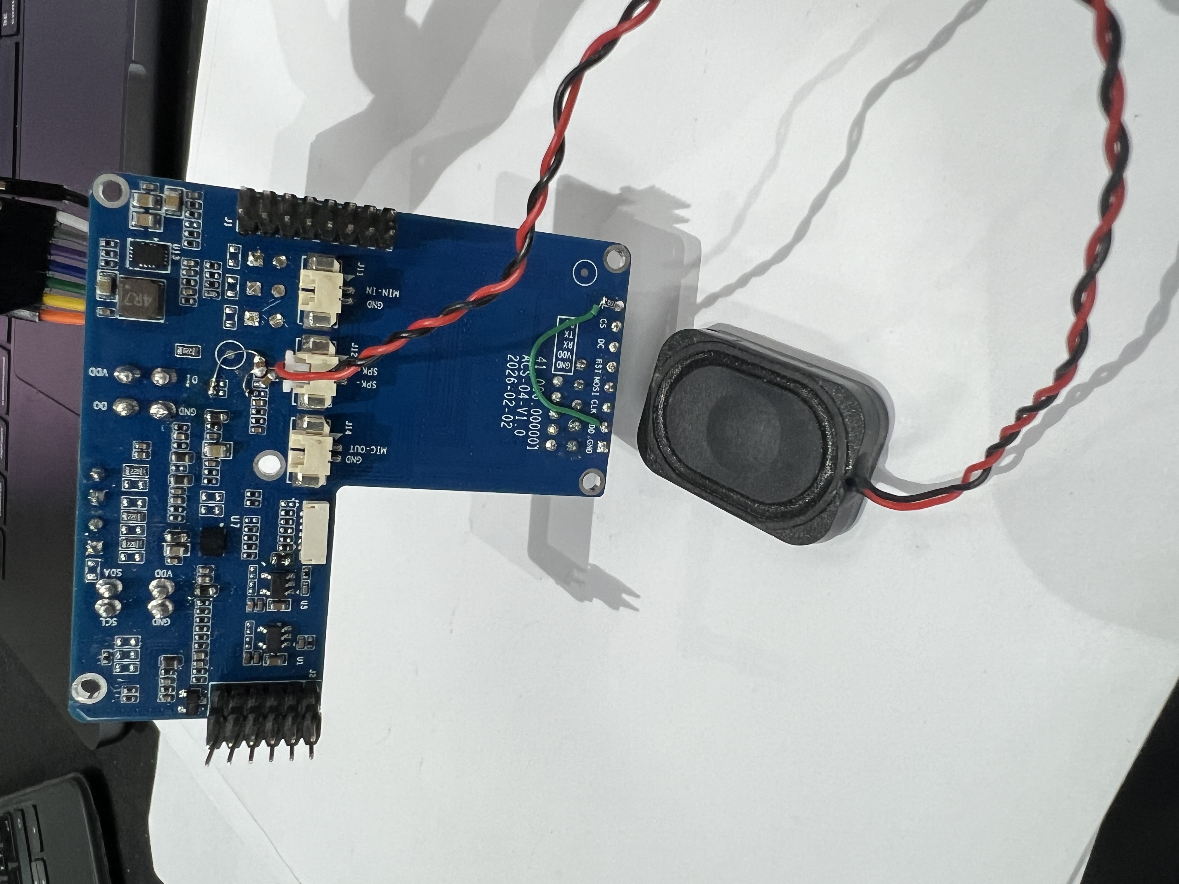 | Speaker (optional) | 1 | HDK-302008ZA-3C13, dynamic type, 30×20mm Rated power 1.5W, impedance 8Ω±15%, sensitivity 90dB (0.5W/0.1m), frequency range Fo–20KHz |
Last updated: 2026-04-01