Quick Start(PoE)
Overview
This tutorial will help you get started with the NeoEyes NE301 PoE version. The PoE (Power over Ethernet) version delivers both data transmission and device power through a standard Ethernet cable, eliminating the need for batteries and making it ideal for long-term outdoor deployment.
Key Advantages of the PoE Version
- Outdoor Waterproof: The PoE power solution removes the battery compartment, and combined with the device's IP67 rating, it is better suited for long-term outdoor deployment
- Continuous Capture: PoE power provides stable and continuous electricity, allowing the device to operate uninterrupted without worrying about battery life
- RTMP Video Streaming: Supports stable, low-latency RTMP video streaming through a wired Ethernet connection
Video tutorial: NE301 PoE Version Setup Guide
Hardware Introduction
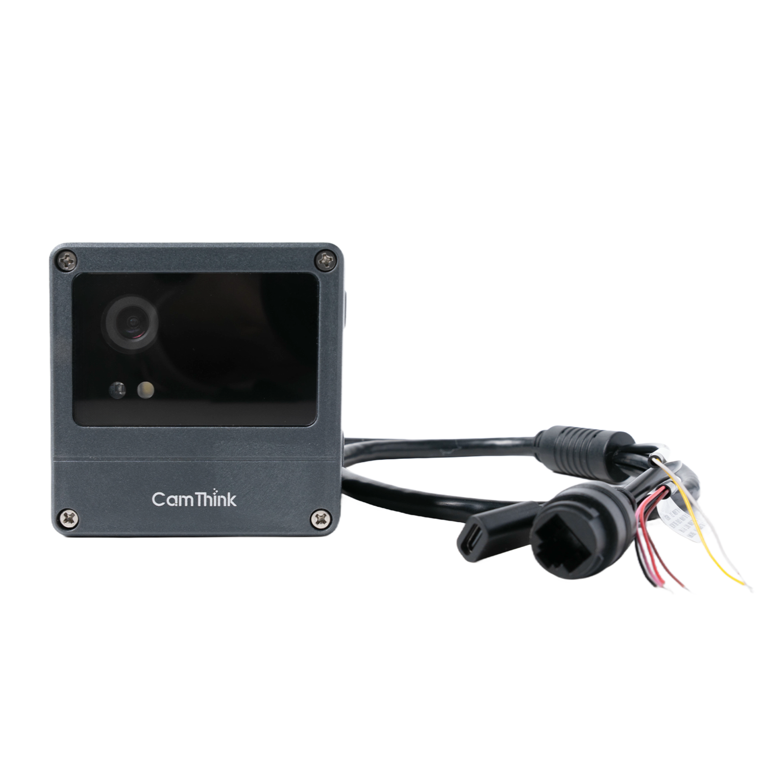
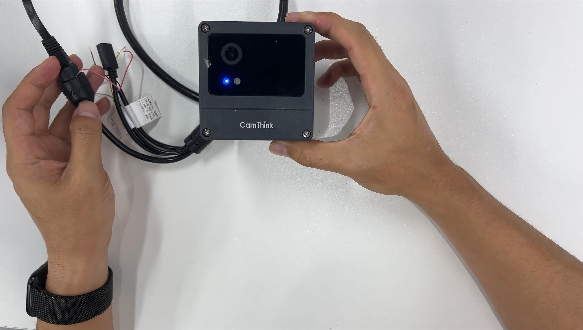
PoE Version Appearance
The NE301 PoE version adds a PoE power module to the standard version. The image below shows the complete device.
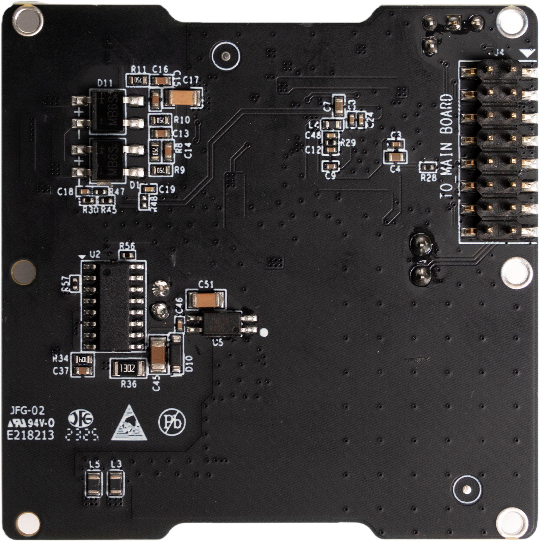
PoE Module Introduction
The PoE expansion board is the core component of the NE301 PoE version. It converts the power delivered through the Ethernet cable to the operating voltage required by the device while providing wired network connectivity.
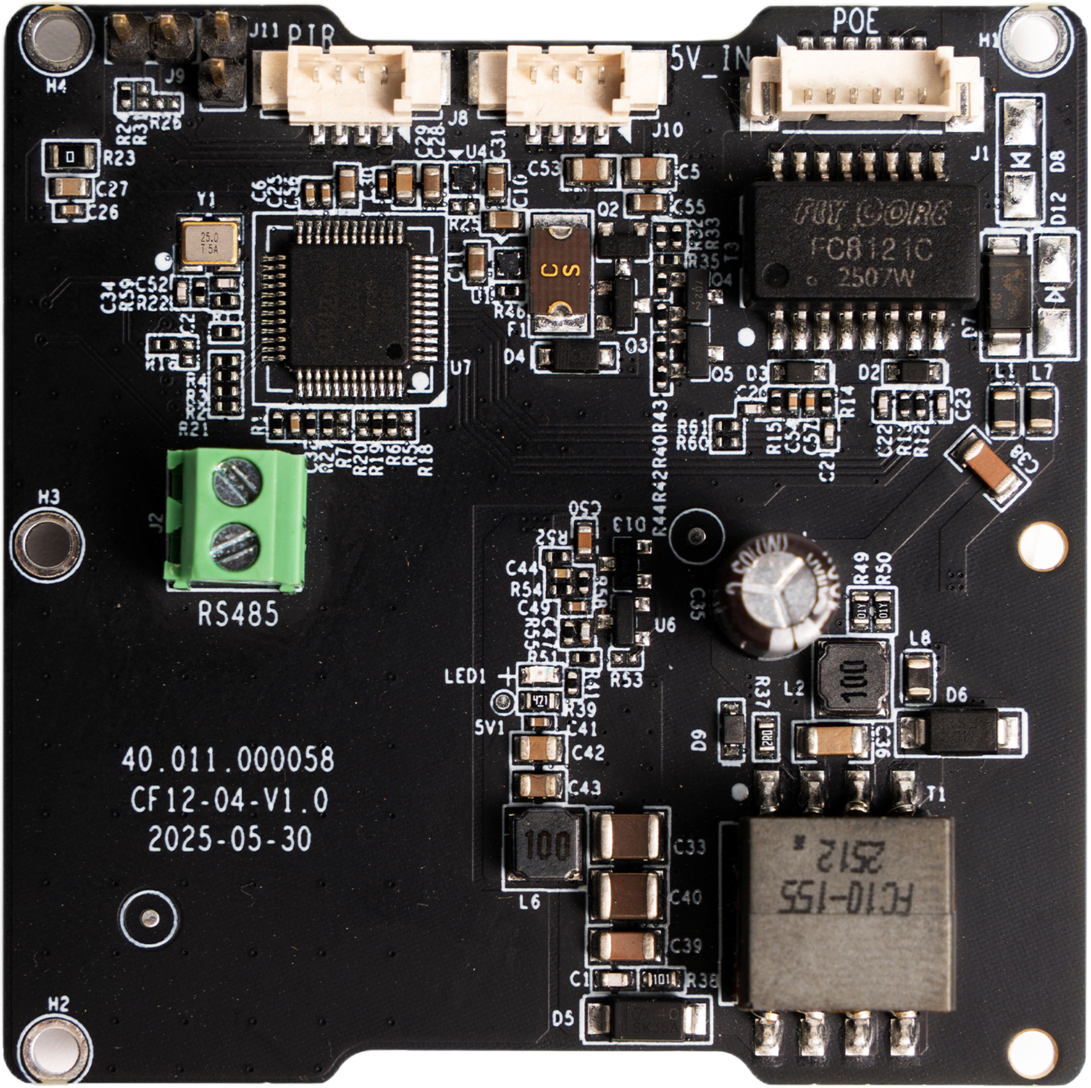
PoE Board Core Interfaces
In addition to PoE power supply, the PoE board provides the following interfaces to expand device connectivity:
| Interface | Description |
|---|---|
| PoE | Ethernet power + wired network, IEEE 802.3af standard |
| Type-C | Wired power supply interface; if a protective enclosure is needed, route through the PoE board, otherwise connect directly to the mainboard |
| Alarm | 4PIN alarm input/output interface with 5V power supply, compatible with 2PIN non-smart PIR sensors |
| RS485 | Industrial-standard serial communication interface, supports RS485 bus device connection |
PoE Power Requirements
The NE301 device operating current is approximately 170-180mA, with a measured PoE voltage of 4.9~5.1V and device power consumption below 10W (source: Product Information). Power supply requirements are as follows:
| Item | Requirement |
|---|---|
| PoE Standard | IEEE 802.3af (15.4W) or above |
| Power Supply Equipment | PoE switch or PoE injector (Midspan) |
| Ethernet Cable | Cat5e or above, outdoor waterproof cable recommended |
Tip: If your deployment environment already has a PoE switch (e.g., surveillance network), the NE301 PoE version can be directly connected to the existing network.
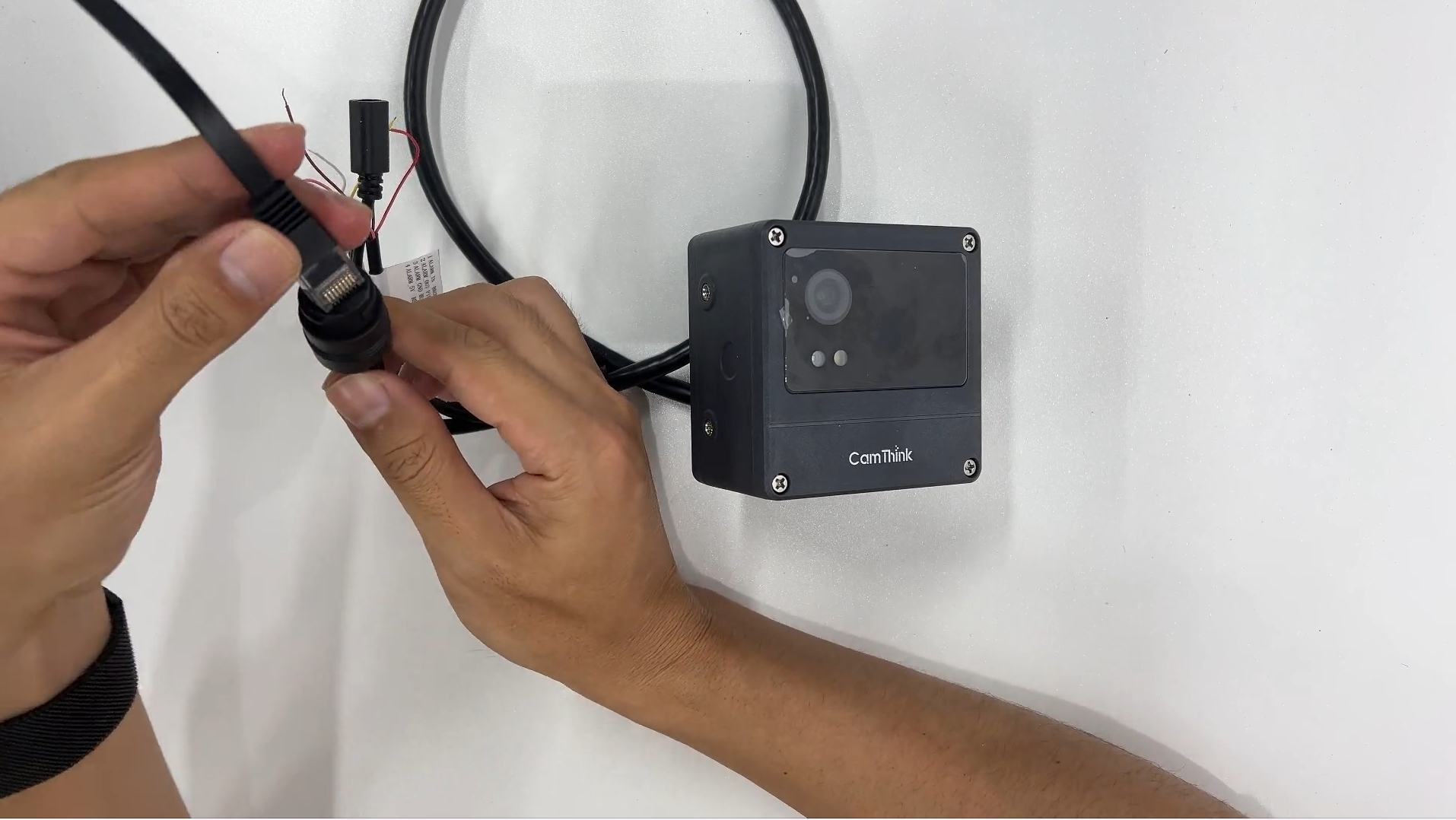
PoE Hardware Connection
Assembly Steps
- Align the PoE module with the corresponding interface on the NE301 mainboard
- Press gently to ensure a secure connection
- Use an Ethernet cable to connect the PoE module to a PoE switch (or PoE injector)
Power-On Confirmation
After connecting the PoE cable, check whether the blue indicator light on the front of the device is on. The blue indicator light indicates that the device has successfully powered on via PoE and started up.
Tip: If the indicator light does not turn on, please check whether the Ethernet cable is properly connected and whether the PoE power supply equipment is functioning normally.
Connection and Login
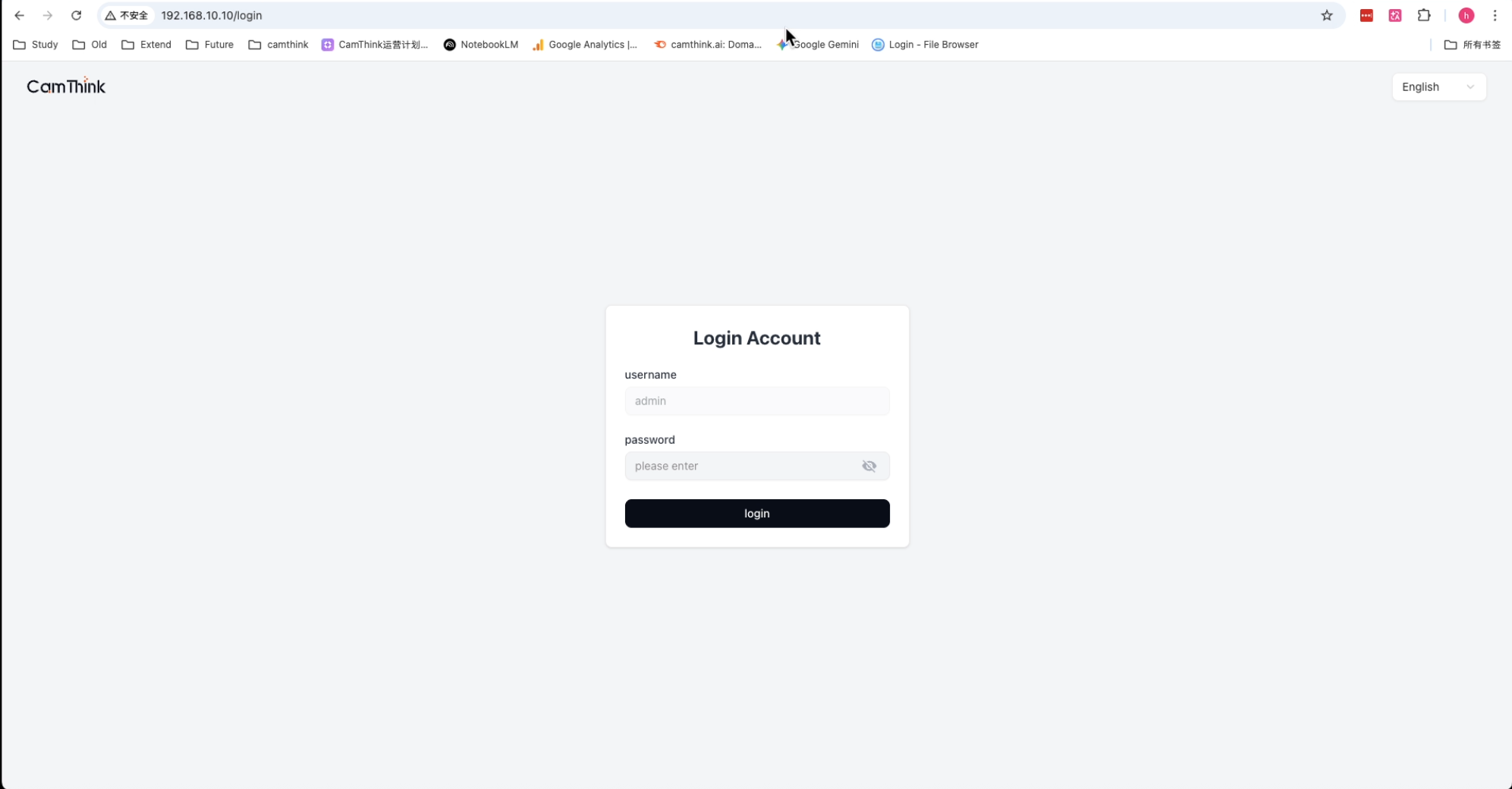
Connect to NE301 WiFi AP
The NE301 PoE version also has a built-in WiFi AP for configuring and managing the device via Web UI. The SSID naming convention for the NE301 WiFi AP is NE301{last 6 hex digits of MAC}.
- Ensure the device is powered via PoE and has started normally (blue indicator light on)
- Find the WiFi AP named
NE301{last 6 hex digits of MAC}in your phone or computer's WiFi list and connect to it - After a successful connection, enter
192.168.10.10in a browser to access the Web management page
Short press the capture button to trigger a capture; long press the button for 2 seconds to wake up the WiFi AP, and the blue system indicator light on the front of the device will turn on. The WiFi AP enters sleep mode after 10 minutes of inactivity by default. If the page disconnects, short press the capture button again to wake it up or adjust the sleep timeout.
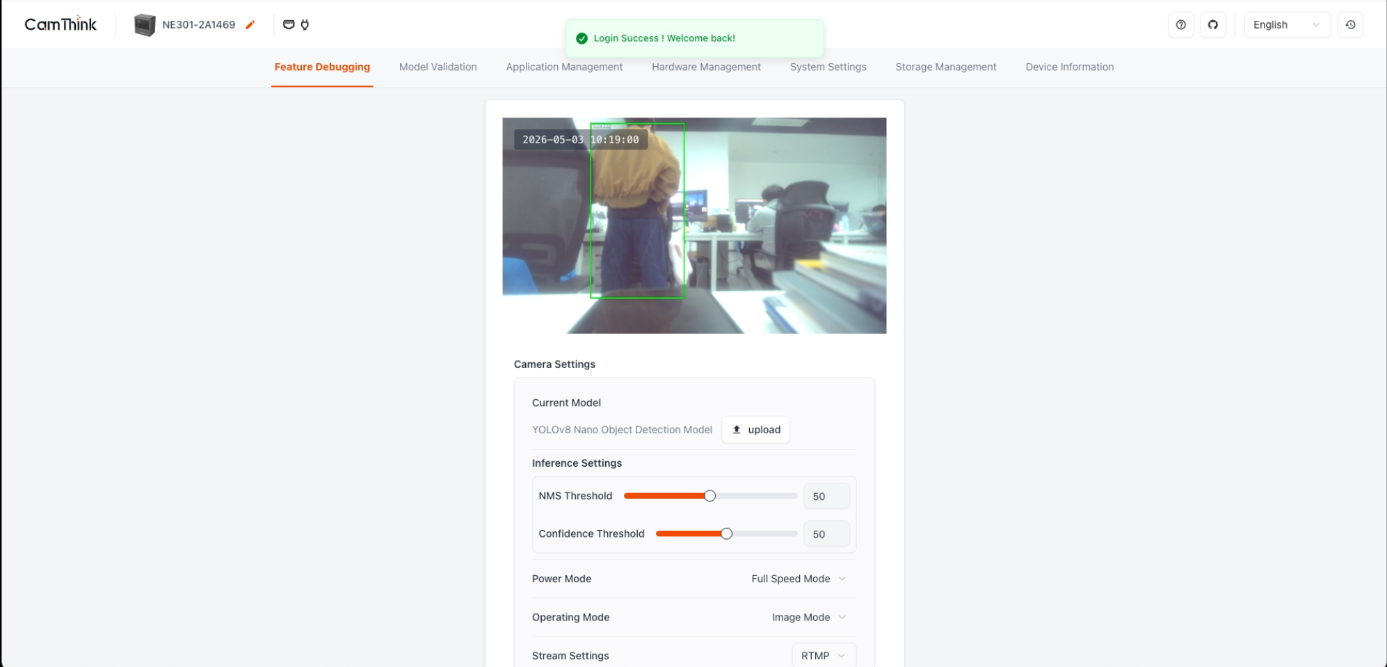
Log in to Web UI
After opening 192.168.10.10 in your browser, you will see the login page. The default password is hicamthink, which can be changed in Main Menu - System Settings - Device Password.
PoE Network Management
Check PoE Connection Status
After logging in to the Web UI, navigate to the network settings page to view the current PoE connection status, including whether the network connection is normal and the current IP address.
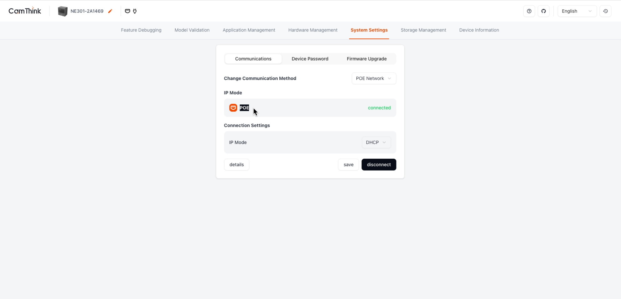
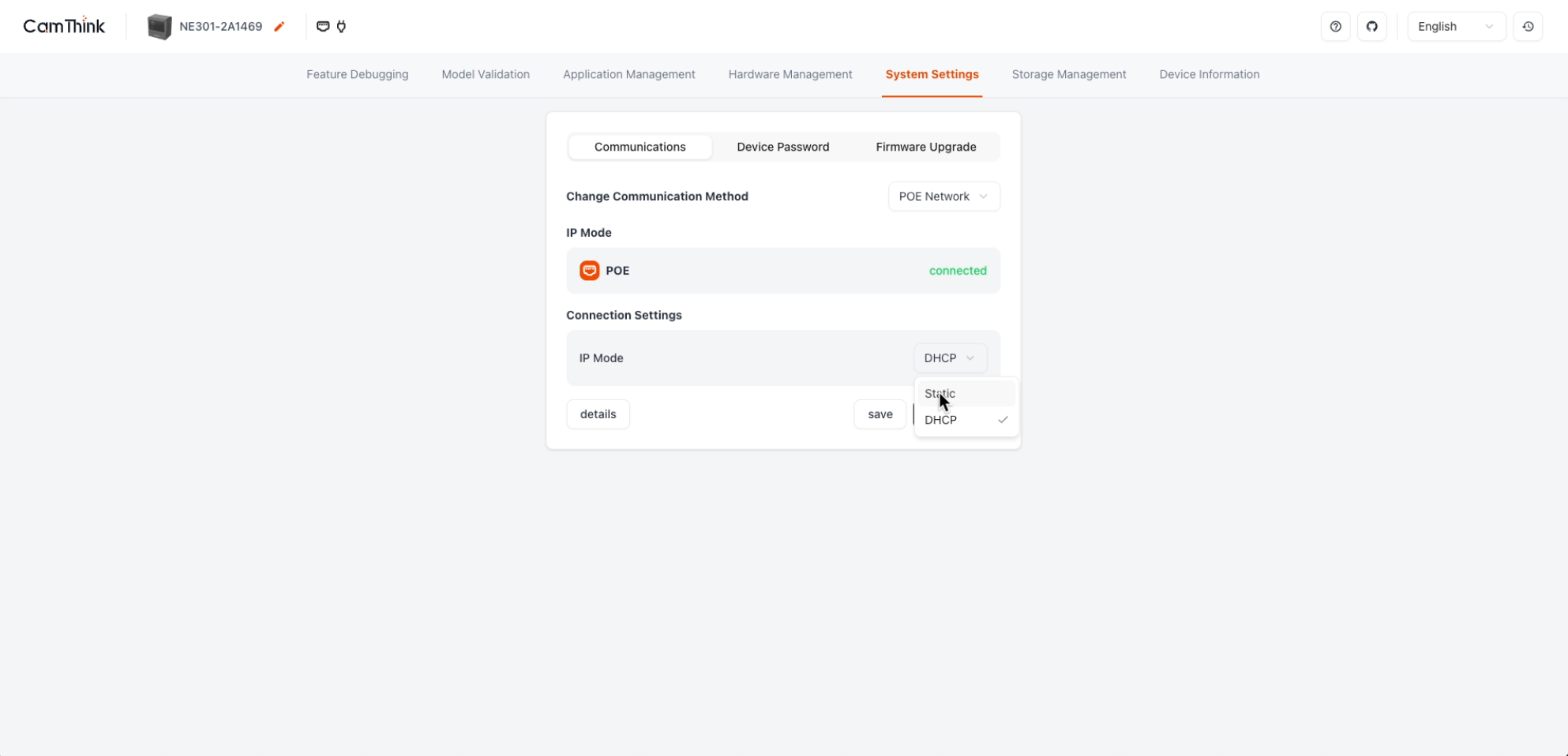
Configure PoE IP Settings
Depending on your network environment, you can configure the PoE IP acquisition method:
- DHCP (default): Automatically obtains an IP address from the router, suitable for most scenarios
- Static IP: Manually specify the IP address, subnet mask, and gateway, suitable for scenarios that require a fixed IP for device management
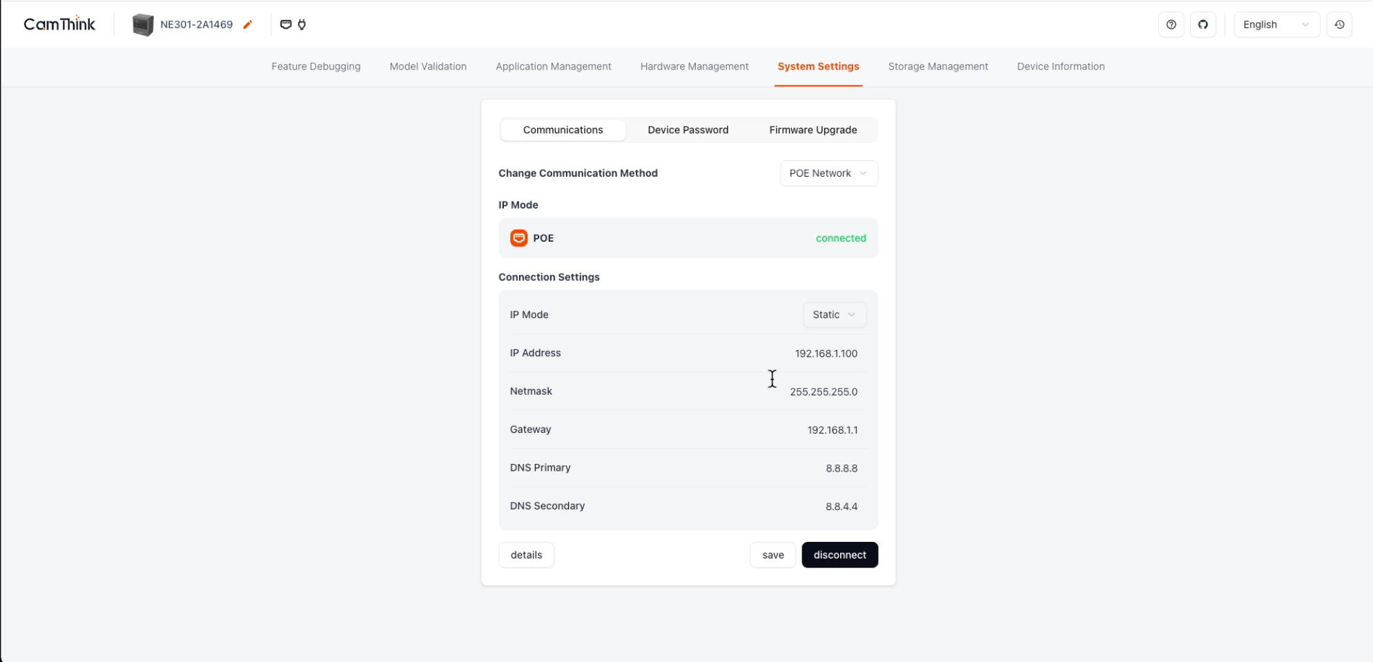
Tip: Once the device is configured with a static IP, other devices on the same LAN can access the NE301's Web UI directly through that IP address without connecting to the WiFi AP.
Typical Application Scenarios
Continuous Capture Mode
With PoE power, the device can operate 24/7. Combined with timed capture, sensor triggers (PIR/radar, etc.), and MQTT data reporting, it enables fully unattended monitoring.
RTMP Video Streaming
Through a wired Ethernet connection, the PoE version can push the device's live feed to a streaming media server, suitable for scenarios that require remote real-time viewing. For detailed configuration, please refer to the RTMP Video Streaming Guide.
Troubleshooting
| Issue | Possible Cause | Solution |
|---|---|---|
| Indicator light not on | PoE power supply abnormal | Check the Ethernet cable and PoE power supply equipment |
| Cannot connect to WiFi AP | Device not started or WiFi AP in sleep mode | Confirm PoE power is normal, long press the button for 2 seconds to wake up WiFi AP |
| PoE web page inaccessible | IP address conflict or no IP obtained | Check network settings, try using DHCP or change to a different static IP |
Related Documentation
- NE301 Product Information
- NE301 Quick Start (Standard Version)
- RTMP Video Streaming Guide
- PIR Sensor Integration
Last updated: 2026-04-08