system-flashing-and-initialization
Hardware Connections
Prerequisites
- NE301 main board × 1
- ST-Link V2 × 1
- 4-pin 1.25 mm JST (male) → 2.54 mm Dupont (female) cable for STM32N6 flashing
- 3-pin 2.54 mm Dupont (female-female) cable for STM32U0 flashing
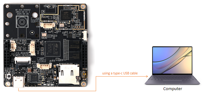
- USB Type-C cable compatible with your PC port (Type-A host requires a C→A cable)
The mainboard contains two MCUs: stm32n6 and stm32u0
Ready for Flashing apps, web, or models to stm32n6
-
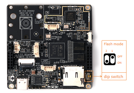
Toggle DIP switch #2 to ON to enter flashing mode. After flashing, switch it back and power-cycle (or press Reset) to boot into runtime mode.
-
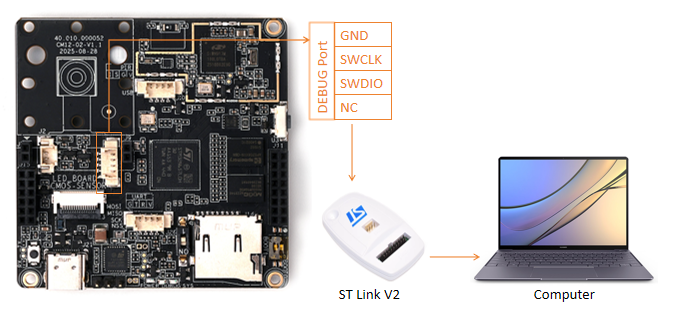
Use the 4-pin adapter cable to connect the ST-Link to the board's DEBUG header, then plug ST-Link into the PC.
-
Connect the board to the PC or a power adapter via USB Type-C.
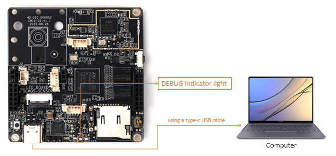
The on-board DEBUG LED stays solid to indicate flashing mode.
Ready for Flashing wakecore to stm32u0
-
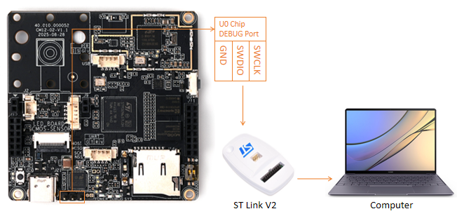
Use the 3-pin Dupont cable to connect the ST-Link directly to the STM32U0 header, then attach ST-Link to the PC.
-
Connect the board to the PC or power adapter via USB Type-C.
Download Firmwares
-
Fetech firmwares from Github
-
Files List
  ne301_FSBL_signed.bin       --> use for stm32n6 FSBL        --> flash addr 0x70000000
  ne301_App_signed_pkg.bin    --> use for stm32n6 App         --> flash addr 0x70100000
  ne301_Web_pkg.bin           --> use for web gui             --> flash addr 0x70400000
  ne301_Model_pkg.bin         --> use for AI model            --> flash addr 0x70900000
  ne301_WakeCore.bin          --> use for stm32u0 wakecore    --> flash addr 0x08000000
Flashing
Flash tools supported
- STM32CubeProgrammer

or CLI
export DKEL="<STM32CubeProgrammer_N6 Install Folder>/bin/ExternalLoader/MX66UW1G45G_STM32N6570-DK.stldr"
STM32_Programmer_CLI -c port=SWD mode=HOTPLUG -el $DKEL -hardRst -w <bin-name>  <flash-addr>
- Script/maker.sh
Script/maker.sh flash <bin-name> <flash-addr>
- make
# Flash all components
make flash
# Flash specific component
make flash-fsbl
make flash-app
make flash-web
make flash-model
make flash-wakecore
Troubleshooting
If you cannot find the NE301 WiFi AP after successful flashing, it might be due to missing WiFi firmware. Please refer to WiFi Firmware Flashing Guide for details.