Sensor Extension Board
The ACS-04 Sensor Extension Board is a standardized sensor expansion module compatible with both the NE101 and NE301 platforms. The board integrates 9 sensors that connect through a unified I2C bus, managed by an open-source driver layer that supports plug-and-play operation and custom sensor integration, providing a flexible hardware foundation for customized solutions.
1. Overview
Supported Platforms
| Platform | Firmware / Driver | Hardware | Usage |
|---|---|---|---|
| NE301 | ✅ Developed, ready to use | ✅ Fully supported | Use the sexp command directly, see Section 4 |
| NE101 | ⏳ Under development | ✅ Interface compatible | Awaiting official firmware, or adapt from open-source drivers, see Section 5 |
Expansion Capabilities
| Method | Description |
|---|---|
| Plug and play | The board pre-integrates 9 sensors — ready to use once connected |
| Custom sensors | Connect any compatible sensor via the I2C bus and write an adapter based on the open-source drivers |
| Display output | Built-in TFT/OLED drivers for real-time sensor data overlay and pseudo-color thermal rendering |
| API integration | Open-source C API (sht3x_init(), vl53l1x_get_result(), etc.) for integration into user applications |
2. Hardware Resources
2.1 Board Appearance
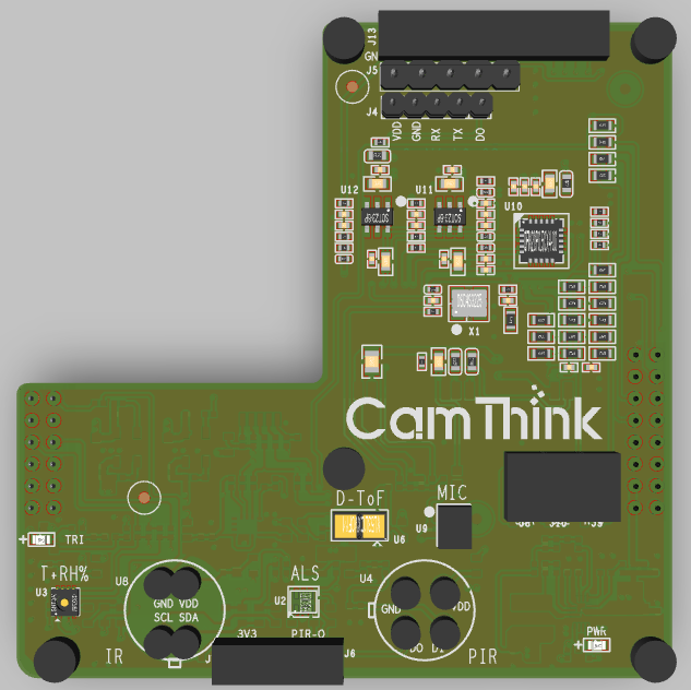
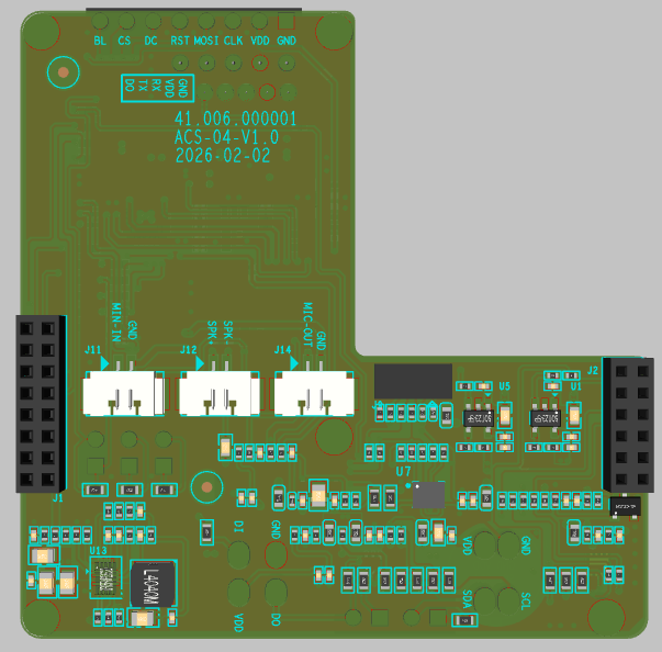
The ACS-04 Sensor Extension Board (V1.0, 2026-02-02) features a compact layout — all sensors and functional circuitry are placed on the front (component side), with the back as the solder side.
2.2 Schematic
Sensor Extension Board Schematic 「Download」
2.3 Integrated Sensors
The board integrates 9 sensors covering temperature/humidity, light, motion, distance, thermal imaging, human presence, mmWave radar, and audio acquisition.
| Sensor | Model | Interface / Address | Capability | Typical Application |
|---|---|---|---|---|
| Temperature & Humidity | SHT3x | I2C 0x44 | Temp ±0.3°C, RH ±2% | Environmental monitoring, storage, overheat protection |
| Ambient Light | LTR-31x | I2C 0x22 | 16-bit visible + IR | Lighting control, day/night switching, intrusion detection |
| 6-axis IMU | LSM6DSR | I2C 0x6a | Accelerometer + gyroscope, ±2g~±16g / ±125~±2000dps | Pose detection, vibration monitoring, fall detection |
| Short-range ToF | VL53L1X | I2C 0x29 | Laser ranging 1.3m (short) / 4m (long) | Proximity detection, gesture recognition, collision warning |
| Long-range Laser | DTS6012M | I2C 0x51 | d-ToF, 18m range (12m@160Klux), 905nm, FOV<2° | Long-range target detection, distance monitoring, perimeter security |
| Thermal Imaging | MLX90642 | I2C 0x66 | 32×24 pixel thermal array, ±1°C, FOV 110°×75° / 45°×35° | Non-contact thermometry, heat distribution, human detection |
| PIR Human Presence | NP624M-F | Digital IO | Digital dual-element, RF interference resistant, 5μA, VIN:1.6~3.6V | Motion detection, security intrusion, auto lighting |
| mmWave Radar | RKB1161LX1 | UART | 24GHz, 68μA, 20×20×1.0mm | Presence detection, occupancy sensing, micro-motion detection |
| MEMS Microphone | LMA3729T381-OY3S | I2S | MEMS MTC, sensitivity -38dB, SNR=63dB | Voice capture, sound detection, environmental audio monitoring |
All I2C sensors share the same I2C bus; a missing sensor does not affect the others.
2.4 Supported Displays
The board also supports the following displays for sensor data visualization (optional, paired with the board):
| Type | Size | Interface | Resolution | Color | Dimensions (mm) |
|---|---|---|---|---|---|
| OLED | 0.96" | I2C, 4PIN | 128×64 | Blue | 24.7(L)×27(W)×11.3(T) |
| TFT | 1.14" | SPI, IPS | 135×240 | 65K | 31.4×28×11.3 |
| TFT | 1.54" | SPI, IPS | 240×240 | 262K | 32(W)×43.7(H)×5.32(T) |
3. Hardware Assembly
Required Hardware
| Component | Description |
|---|---|
| Dev board (NE301 / NE101) | NE301 ships with system firmware; NE101 requires adapted firmware |
| Sensor Extension Board | Pre-integrated with 9 sensors |
| Display | 0.96" OLED / 1.14" TFT / 1.54" TFT (optional) |
| USB-C cable | For serial debugging and power |
| Debugging tool | Serial terminal (e.g., minicom, PuTTY) |
Installation Steps
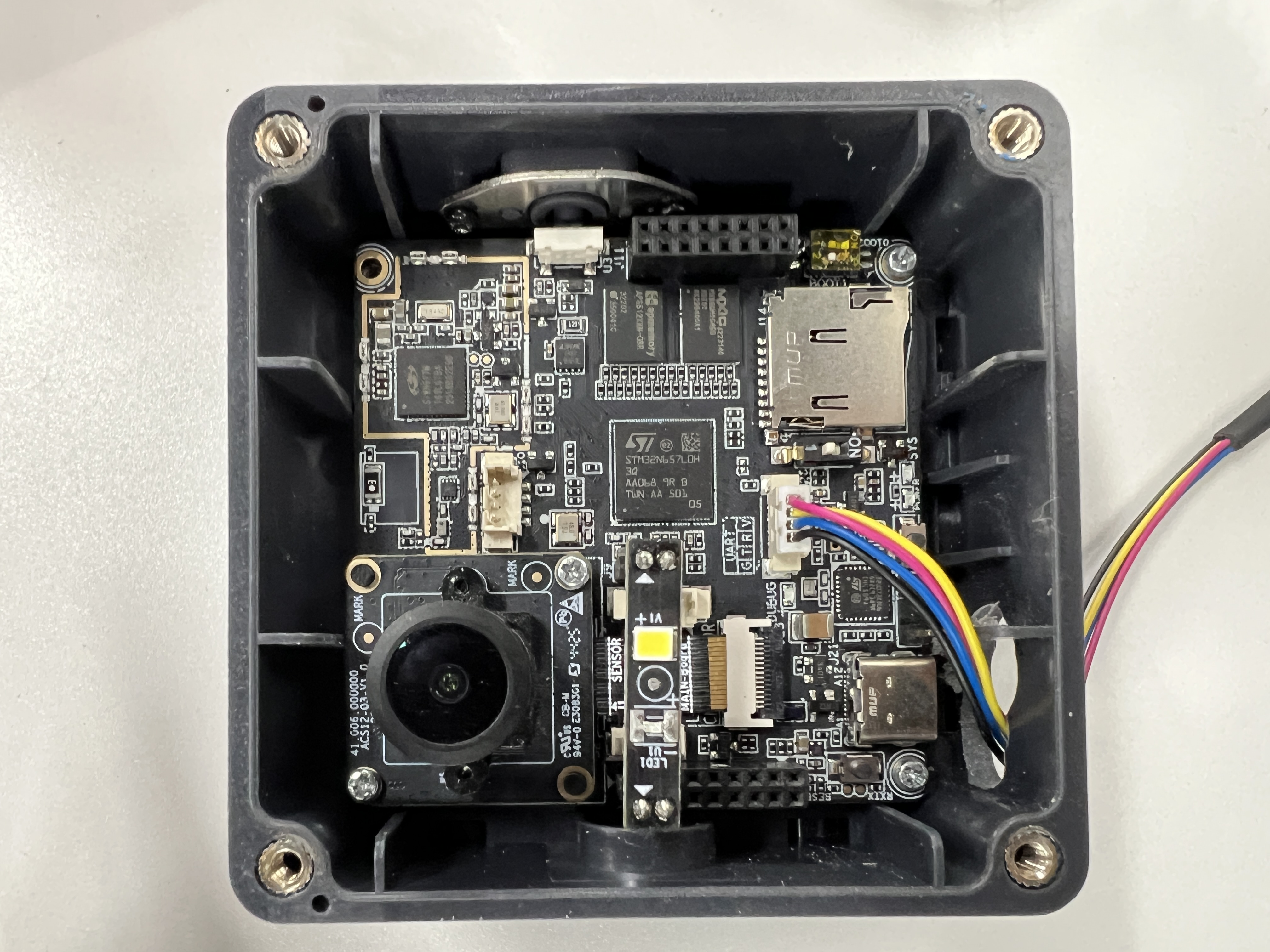
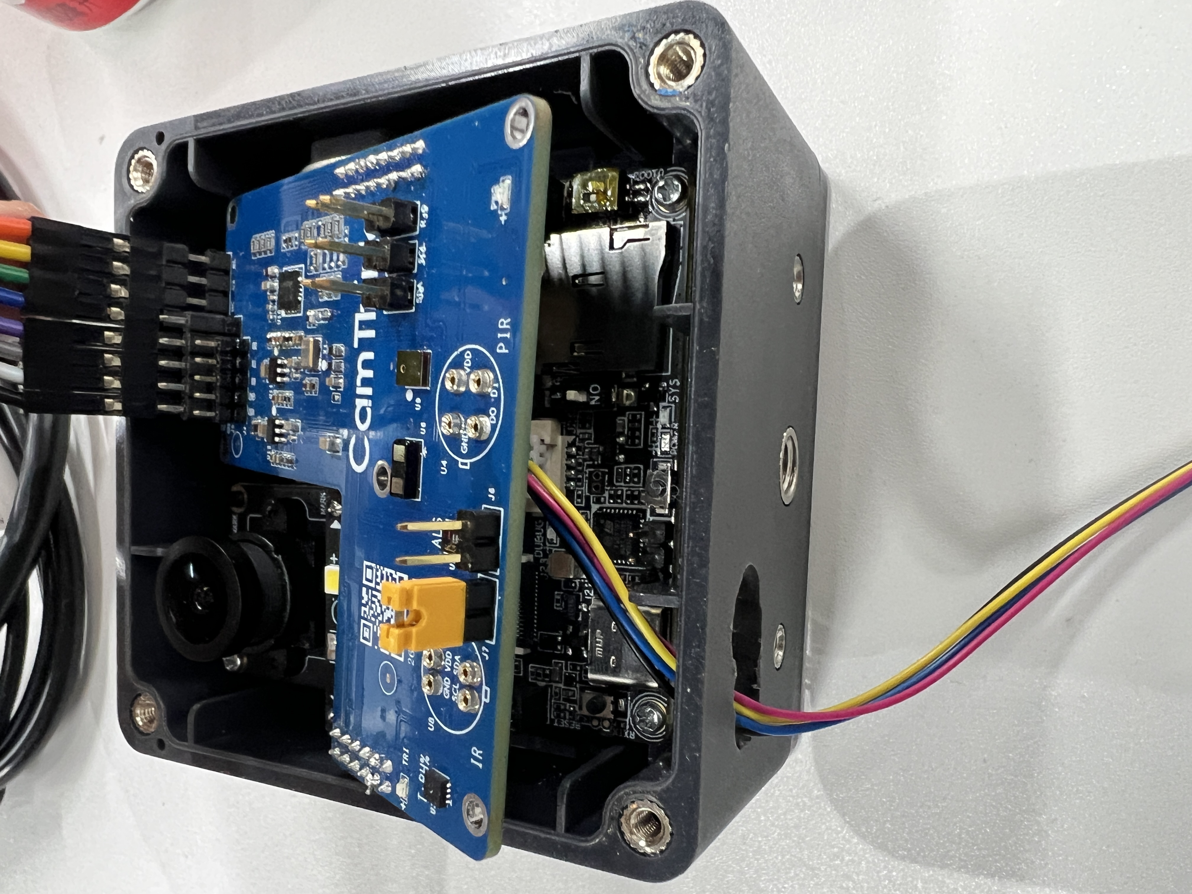
Step 1: Align the Sensor Extension Board with the main board's expansion connector and gently press it into place.
Step 2: Connect the TFT display to the SPI display interface on the extension board.
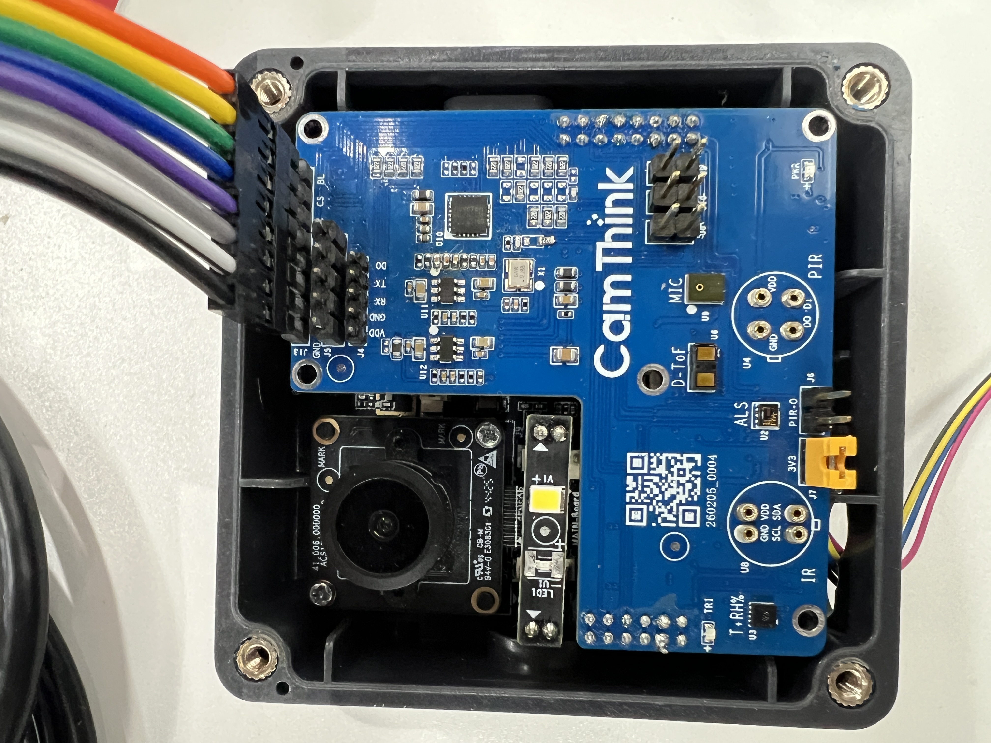
Step 3: Connect the dev board via USB-C and open a serial terminal.
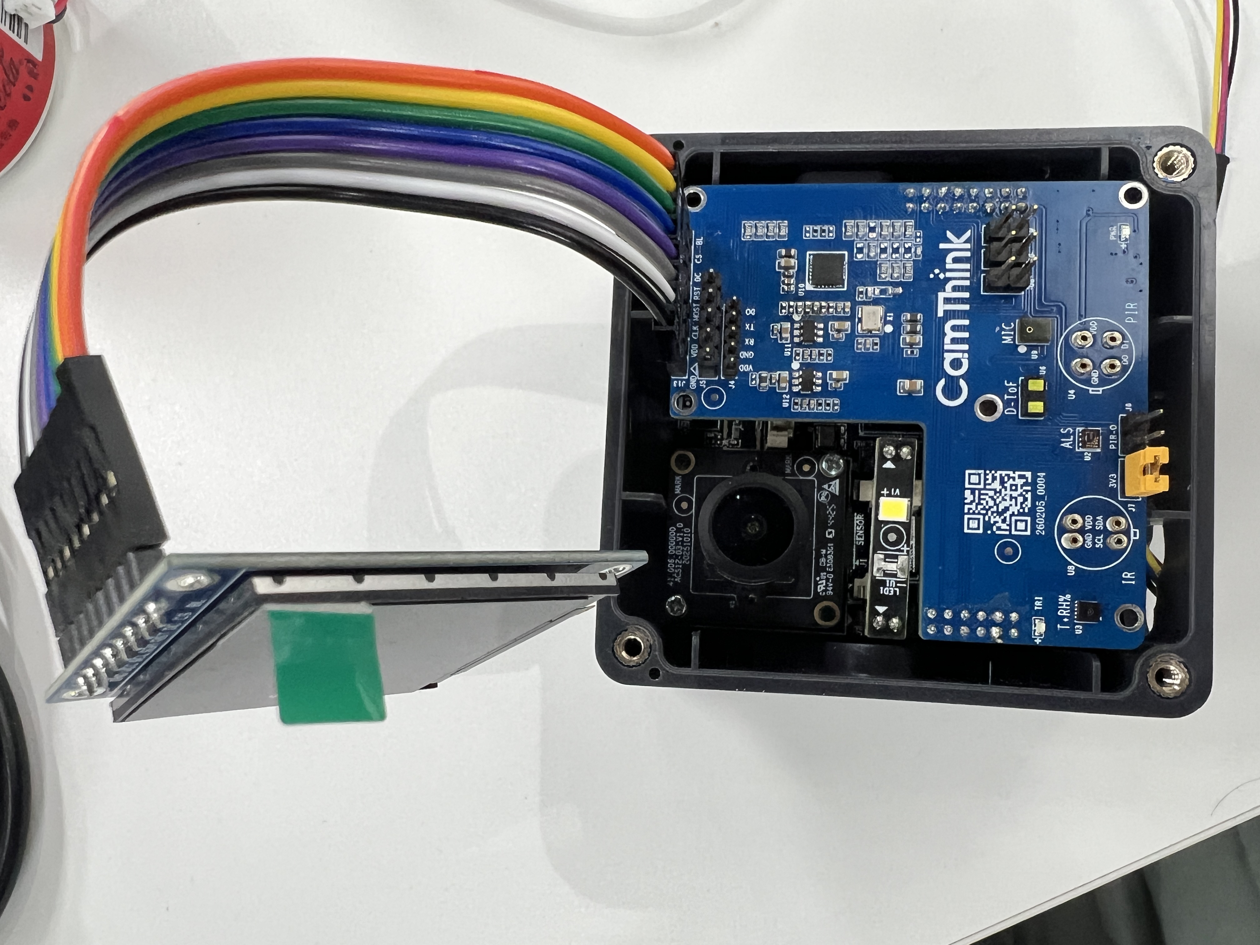
After assembly, the complete setup looks like this:
4. NE301 Platform Quick Start
The commands and behavior in this section are based on the NE301 platform firmware. NE301 sensor drivers are fully open-source and integrated into the system firmware — ready to use out of the box. For the NE101 platform, see Section 5.
4.1 Scan the I2C Bus
After connecting to the serial terminal, run the I2C scan command to confirm all sensors are online:
AICAM> i2c_tool detect
Scanning I2C bus 1, address range 0x03-0x77
      00 01 02 03 04 05 06 07 08 09 0a 0b 0c 0d 0e 0f
00:          -- -- -- -- -- -- -- -- -- -- -- -- --
10: -- -- -- -- -- -- -- -- -- -- 1a -- -- -- -- --
20: -- -- 22 -- -- -- -- -- -- 29 -- -- -- -- -- --
30: -- -- -- -- -- -- -- -- -- -- -- -- -- -- -- --
40: -- -- -- -- 44 -- -- -- -- -- -- -- -- -- -- --
50: -- -- -- -- -- -- -- -- -- -- -- -- -- -- -- --
60: -- -- -- -- -- -- 66 -- -- -- 6a -- -- -- -- --
70: -- -- -- -- -- -- -- --
Complete sensor address list:
| Address | Sensor | Address | Sensor |
|---|---|---|---|
| 0x1a | NAU881x audio codec | 0x44 | SHT3x temp/humidity |
| 0x22 | LTR-31x ambient light | 0x51 | DTS6012M laser ranging |
| 0x29 | VL53L1X ToF ranging | 0x66 | MLX90642 thermal imaging |
| 0x6a | LSM6DSR 6-axis IMU |
4.2 Start Sensor Data Acquisition
Run the following command to start sensor data acquisition and TFT display:
AICAM> sexp start
This initializes all sensors (I2C bus 1), starts a 200ms sensor read loop, and displays all sensor data in real time on the TFT:
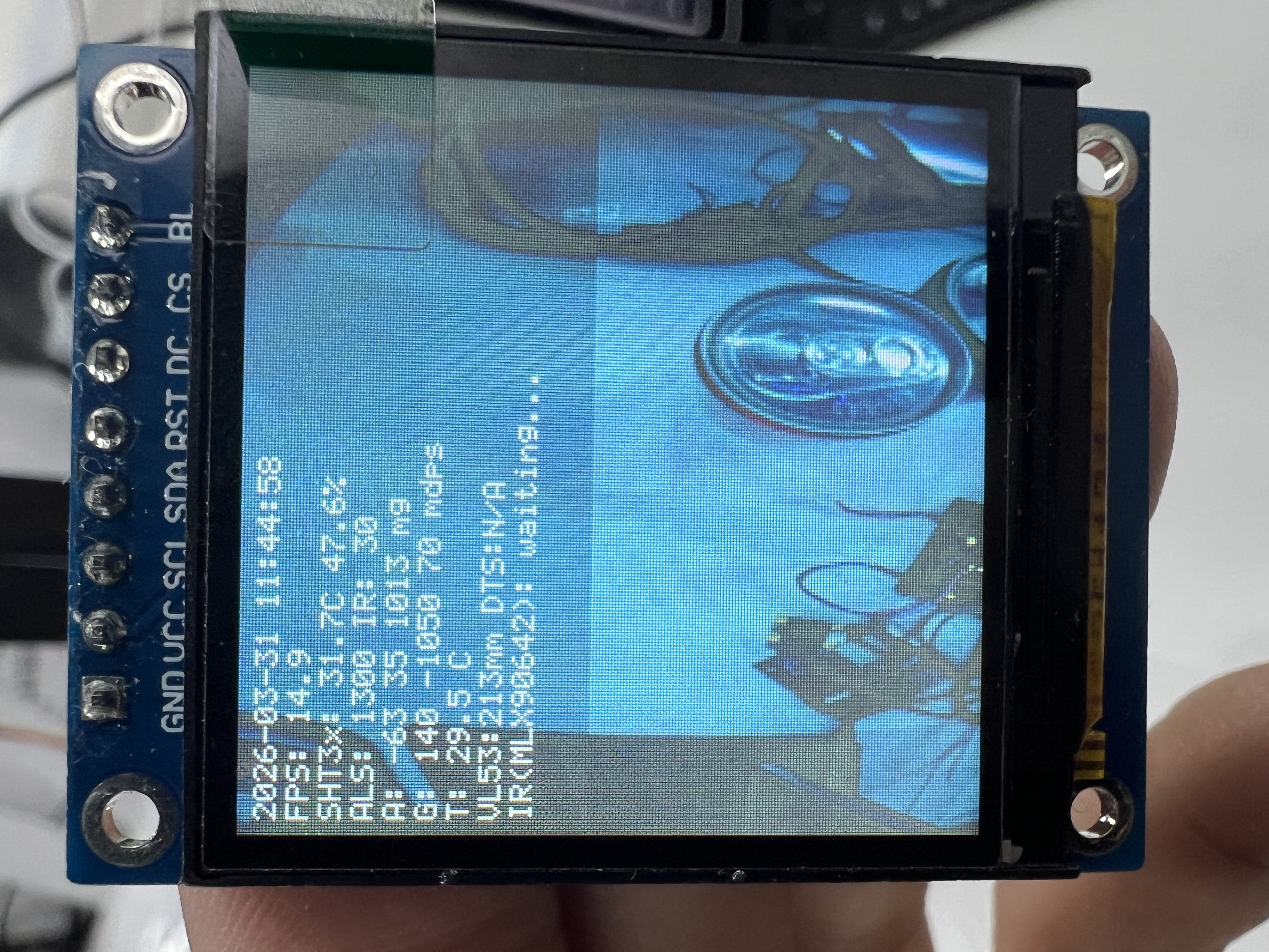
4.3 View Sensor Data
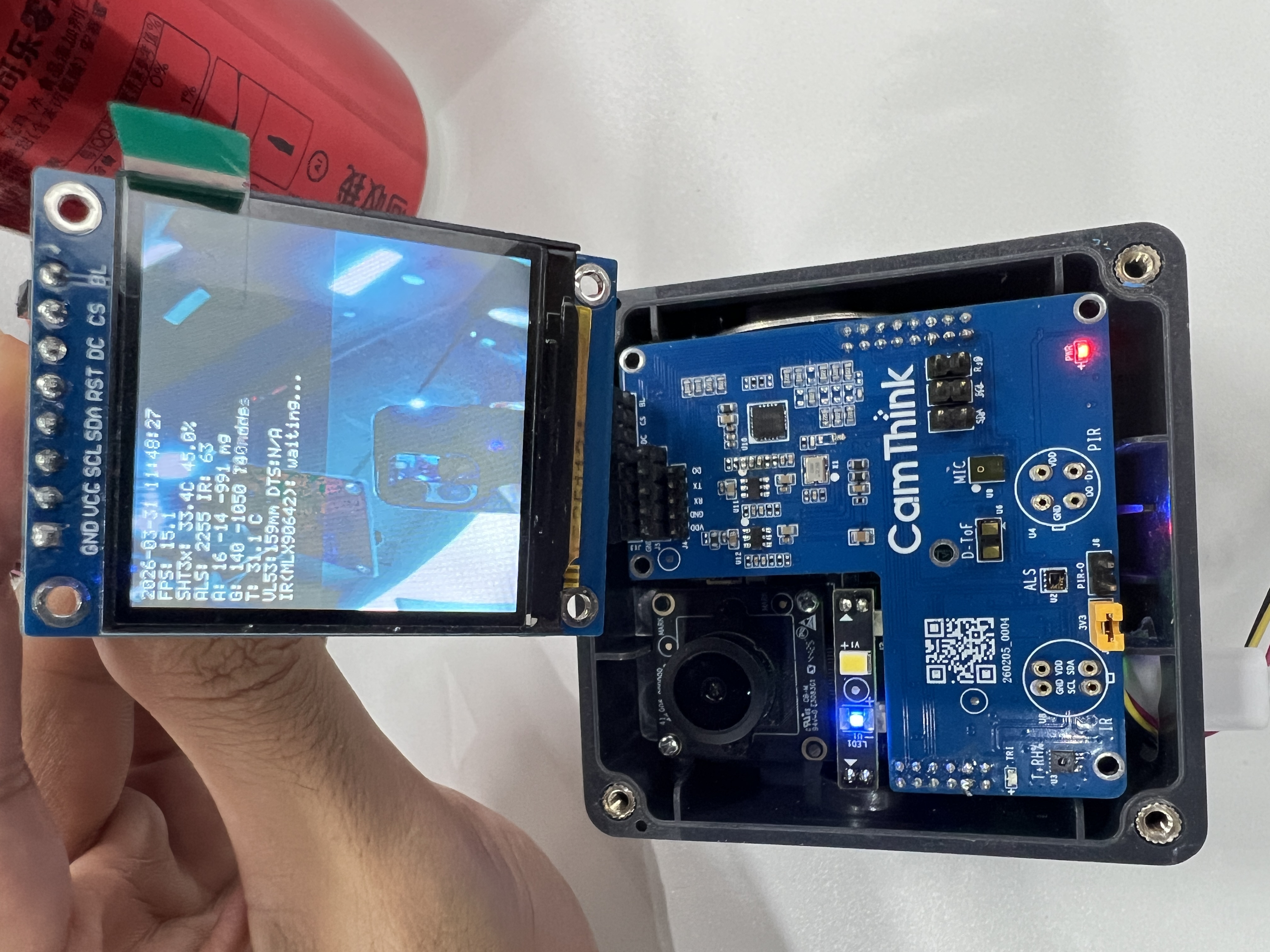
The text area at the top of the TFT shows real-time readings from each sensor:
SHT3x: 33.4 C 45.0%       ← Temperature & humidity
ALS: 2255 IR: 63           ← Ambient light (visible + IR)
VL53:159 mm                ← Short-range ToF ranging
DTS:N/A mm                 ← Long-range laser ranging
A: 16 -14 -991 mg          ← Accelerometer (3-axis)
G: 140 -1050 140 mdps      ← Gyroscope (3-axis)
4.4 Try Thermal Imaging
Run the following command to start thermal imaging mode:
AICAM> sexp start ir
This starts the MLX90642 thermal array (32×24 pixels) and renders a pseudo-color thermal image (blue→green→yellow→red) on the lower half of the TFT, while the top half continues to show sensor text data.
The top of the TFT shows thermal statistics:
MLX: min 16.4 C max 28.8 C avg 21.6 C
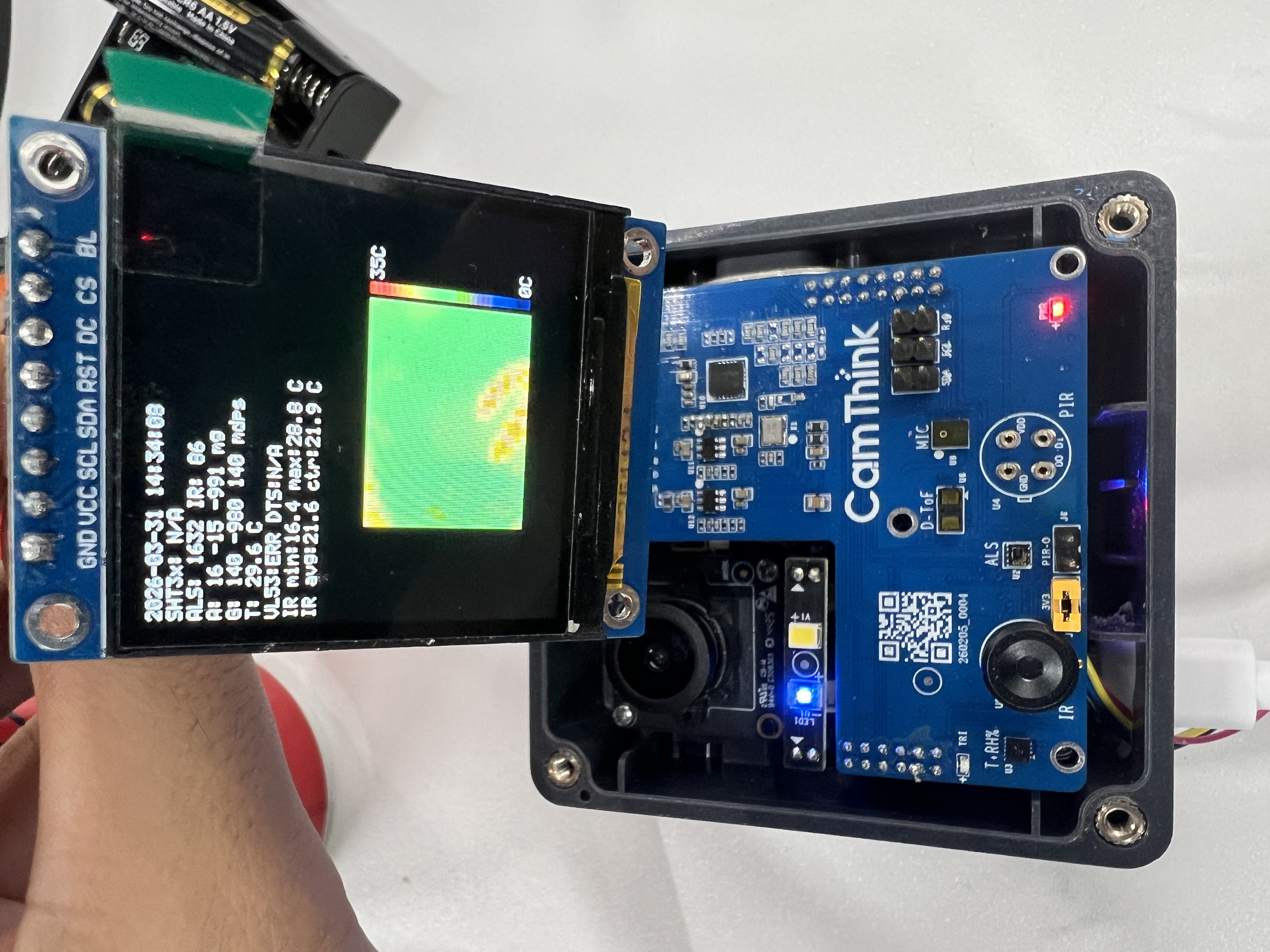
Move your hand near the sensor area to observe the temperature change in real time.
4.5 Stop Data Acquisition
AICAM> sexp stop
5. NE101 Platform Notes
The Sensor Extension Board is hardware-adapted for the NE101 platform (NE100-MB01 dev board) — the pinout and electrical characteristics are identical to NE301, so it connects physically without modification.
Current limitation: NE101's sensor firmware (including drivers) is still under development, and the system does not yet integrate sensor commands such as sexp and i2c_tool. Therefore, the quick-start flow described above cannot currently be run directly on NE101.
Adaptation paths:
- Wait for official firmware: NE101 sensor drivers will ship in a future firmware release, enabling direct use.
- Self-adaptation: All NE301 sensor drivers are open-source. Developers can use the I2C bus abstraction and driver framework as a reference to adapt the sensors to the NE101 platform — see Section 6 for the source structure and CLI debug commands.
6. Developer Resources
Driver Source Structure
NE301's sensor drivers are fully open-source in C, located in the NE301 GitHub repository under Custom/Hal/SensorExt/. It includes the I2C bus abstraction, individual sensor drivers, TFT display output, and integration examples. This source also serves as a reference blueprint for NE101 adaptation.
Source path: Custom/Hal/SensorExt/
SensorExt/
├── i2c_driver/           # I2C bus abstraction layer
├── sht3x/                # SHT3x temperature/humidity driver
├── ltr_31x/              # LTR-31x ambient light driver
├── lsm6dsr/              # LSM6DSR 6-axis IMU driver
├── vl53l1x/              # VL53L1X ToF driver
├── dts6012m/             # DTS6012M laser ranging driver
├── mlx90642/             # MLX90642 thermal imaging driver
├── tft_st7789v/          # TFT display driver
└── sensor_exemple/       # Integration example (sexp command)
Sensor Debug Command Reference
CLI debug commands available for each sensor on the NE301 platform (also available on NE101 after adaptation):
| Sensor | CLI Debug Command |
|---|---|
| SHT3x Temp/Humidity | sht3x init → sht3x read → sht3x deinit |
| LTR-31x Ambient Light | als init → als read → als deinit |
| LSM6DSR 6-axis IMU | lsm6dsr init → lsm6dsr read → lsm6dsr deinit |
| VL53L1X ToF | vl53l1x init → vl53l1x start → vl53l1x read |
| DTS6012M Laser Ranging | dts6012m init → dts6012m read → dts6012m deinit |
| MLX90642 Thermal Imaging | mlx90642 init → mlx90642 measure → mlx90642 deinit |
| RKB1161LX1 mmWave Radar | Driver under development |
| LMA3729T381-OY3S MEMS Microphone | Audio pipeline integration |
7. Customization
The Sensor Extension Board demonstrates the platform's baseline environmental sensing capabilities. The board supports flexible sensor selection based on actual requirements, and a custom top cover can be tailored for different heights and display needs. The driver source is fully open-source — developers can build their own business logic, or contact CamThink for customized development. For more information, contact our Sales team.
Last updated: 2026-07-13