Accelerometer & Gyroscope
Overview
The STMicroelectronics LSM6DSR is a high-performance 6-axis inertial measurement unit (IMU) integrating a 3D digital accelerometer and a 3D digital gyroscope. With an embedded machine learning core, programmable finite state machines (FSM), and Sensor Hub functionality, this chip excels in motion tracking, AR/VR, optical image stabilization, and industrial IoT applications.
1. Product Overview
1.1 Key Features
- 6-axis integration: 3D digital accelerometer + 3D digital gyroscope, single-chip solution
- Ultra-low power: Current as low as microamp level in low-power mode, suitable for battery-powered devices
- Multi-interface support: SPI, I2C, MIPI I3CSM for flexible adaptation to different host platforms
- Embedded intelligent features: Pedometer, motion detection, tilt detection, free fall, and other algorithms
- Programmable FSM: 16 independent finite state machines supporting custom motion recognition logic
- Sensor Hub: Connects up to 6 sensors (2 internal + 4 external) for centralized data acquisition
- Smart FIFO: 9 KB capacity with data compression support (up to 3×), reducing host wake-up frequency
1.2 NE301 Application Scenarios
In the NE301 sensor expansion board, the 6-axis IMU serves as an attitude and vibration sensor, capable of detecting device mounting attitude, displacement, and vibration events. When device movement or abnormal vibration is detected, it can trigger NE301 snapshot capture and report alarms via MQTT; attitude data can also be used for image stabilization or device status monitoring.
| Application Scenario | Description |
|---|
| Device Security | Detects NE301 being moved or collided, triggering alarm snapshots |
| Installation Calibration | Reads attitude data to assist in adjusting NE301 mounting angle |
| Vibration Detection | Monitors abnormal device vibration, triggering event snapshots and reporting |
| Device Monitoring | Long-term recording of device attitude changes to evaluate installation stability |
2. Specifications
2.1 Basic Parameters
| Parameter | Specification |
|---|
| Model | LSM6DSR |
| Manufacturer | STMicroelectronics |
| Type | 6-axis Inertial Measurement Unit (IMU) |
| Package | LGA-14L (2.5 × 3.0 × 0.83mm) |
| Supply Voltage | 1.71V ~ 3.6V |
| Communication Interface | SPI / I2C / MIPI I3CSM |
| Operating Temperature | -40°C ~ +85°C |
| Order Number | LSM6DSRTR (Tape & Reel) |
Accelerometer
| Parameter | Specification |
|---|
| Range | ±2 / ±4 / ±8 / ±16 g (user selectable) |
| Data Output | 16-bit |
| Noise Density | Typical value varies with range |
Gyroscope
| Parameter | Specification |
|---|
| Range | ±125 / ±250 / ±500 / ±1000 / ±2000 / ±4000 dps |
| Data Output | 16-bit |
| Extended Full Scale | Up to 4000 dps |
Embedded Functions
| Function | Description |
|---|
| Smart FIFO | 9 KB, supports compression, up to 3× capacity |
| Advanced Pedometer | Step detection and step counting |
| Significant Motion Detection (SMD) | Detects large-amplitude motion events |
| Tilt Detection | Device tilt angle change detection |
| Programmable FSM | 16 independent finite state machines |
| Standard Interrupts | Free fall, wake-up, 6D/4D orientation, single and double tap |
| Embedded Temperature Sensor | On-chip temperature monitoring |
| Sensor Hub | Up to 6 sensors (2 internal + 4 external) |
| S4S Sensor Sync | Multi-sensor time synchronization |
2.3 Operating Conditions
| Parameter | Specification | Description |
|---|
| Operating Temperature | -40°C ~ +85°C | Full temperature range |
| Storage Temperature | -40°C ~ +85°C | Non-operating state |
| Supply Voltage | 1.71V ~ 3.6V | Normal operating range |
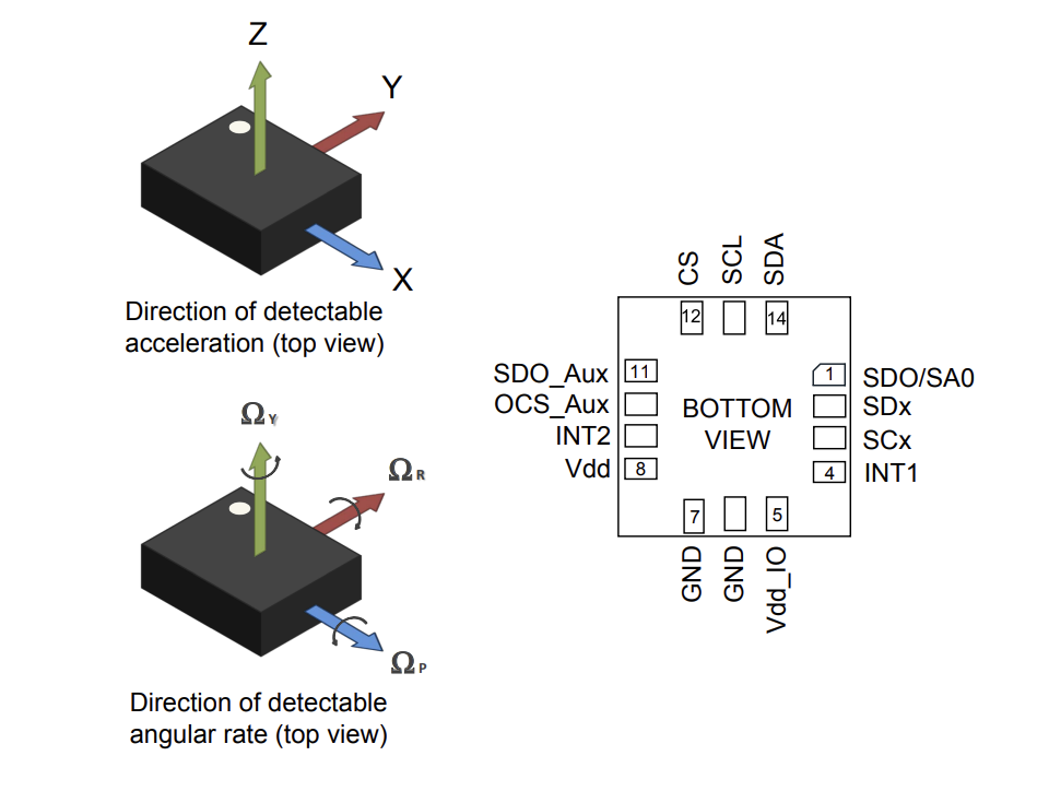
3. Pin Definition
The LSM6DSR uses an LGA-14L package with the following pin definitions:
| Pin | Name | Description |
|---|
| 1 | SDO/SA0 | SPI data output / I2C address selection |
| 2 | SDx | I2C serial data / Auxiliary SPI data |
| 3 | SCx | I2C serial clock / Auxiliary SPI clock |
| 4 | INT1 | Programmable interrupt 1 |
| 5 | Vdd_IO | I/O pin power supply |
| 6 | GND | Ground |
| 7 | GND | Ground |
| 8 | Vdd | Main power supply |
| 9 | INT2 | Programmable interrupt 2 / Data enable (DEN) |
| 10 | OCS_Aux | Auxiliary SPI chip select (float if unused) |
| 11 | SDO_Aux | Auxiliary SPI data output (float if unused) |
| 12 | CS | SPI chip select / I2C mode selection (active low) |
| 13 | SCL | I2C/MIPI I3CSM clock / SPI clock |
| 14 | SDA | I2C/MIPI I3CSM data / SPI data input |
Address selection: When the SA0 pin is connected to logic low, the I2C slave address is 0x6A; when connected to logic high, the slave address is 0x6B.
| Item | Information |
|---|
| Document Version | v1.0 |
| Last Updated | 2026-04-08 |